Week 12:Project-1-Meshing of Door Inner Panel Challenge
AIM: -To create a mesh on a door side panel by performing a geometric clean-up and assigning thickness properties to all the meshed elements.
OBJECTIVE: -
- Import the model and organise the components.
- Creating a criteria file.
- Creating a duplicate component and organise the surface.
- Extraction of mid surface from the duplicate component.
- Reference with parent the surface created will be checked.
- Missing surface is created by using offset from parent component.
- Selecting the surfaces with similar thickness individual.
- Defeaturing the rib components with fillet radius less than 1mm.
- Creating a mid-surface using final edit tools from midsurface panel.
- Using extent option and connecting the ribs to the mid surface.
- Checking of the midsurface and providing cut lines to have proper mesh flow.
- Creating section of the components into mesh region.
- Check for trias and rotational quads.
- Elimination of trias by rebuild mesh and automesh.
- Performing quality index operation drag trias out and smoothing the dragged area.
- Check for element quality criteria and fix them by projecting the node for warpage and element for skew, min and Max length.
- Check for free edges and equivalence
- Creating properties and adding thickness to the mesh.
- Checking for normal and t connections.
- Detailed 2d view updating and assigning thickness.
- Check for Tria percentage.
THEORETICAL EXPLAINATION: -
- Door panels serve as an interface between the interior of the car and the inner workings of the door, and between vehicle occupants and the door shown in fig 1.1.
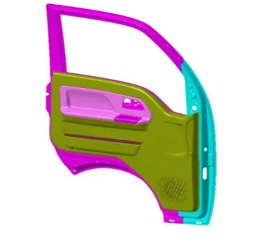
fig 1.1.
- They are expected to meet a variety of design specifications regarding safety, aesthetics, and functionality. In addition, they are expected to continue the material theme of the dashboard and pillars while concealing intricate electrical and mechanical components for operating locks, windows, and other features.
- The door panel has evolved from a simple two-part system of latch and simple winding mechanism to a more sophisticated enclosure. Doors currently have an inner full-width panel consisting of electronic windows, central locking system, and speakers.These panels typically consist of a foamed core covered with either textiles or plastics shown in fig 1.2.
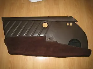
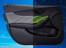
fig 1.2
- Conventionally, door panels as shown in 1.2 consisted of polyvinyl chloride (PVC) or polyurethane foamed core with appropriate textile fabric coverings. Subsequently, there was a shift toward thin-wall moldings of ABS or PP backed by textiles in order to manufacture a contour-backed panel with recesses.
- This is primarily because integrated injection-molded door panel assemblies reduce the need for other energy-absorbing materials, resulting in cost reduction for manufacturers due to simplification of door construction.
- Currently honeycomb-based plastics are attracting attention due to their tougher, lighter, and better acoustic properties. Fig 1.3 gives a list of plastics used by various car manufacturers in making door panels.
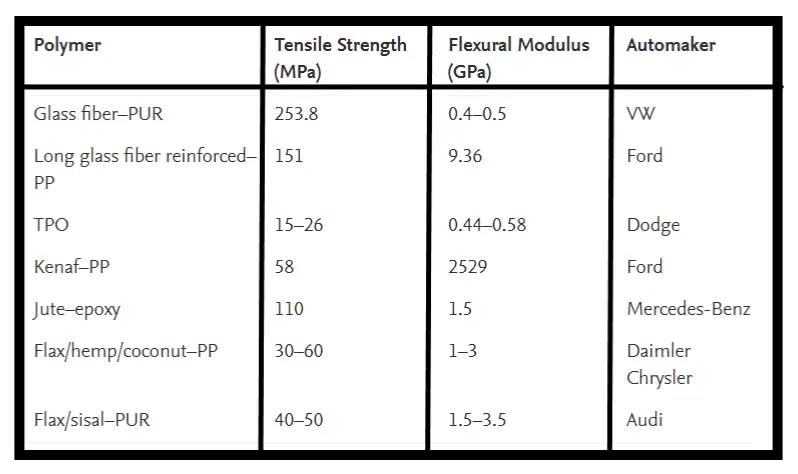
fig 1.3
PROCEDURE:-
*The import of the model is been done by Model components for the Side door panel as shown in fig1.4.
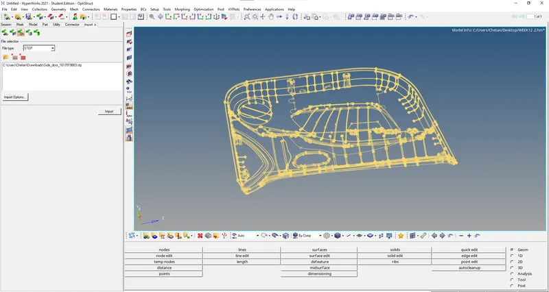
fig1.4.
*The Duplicate is created and the component is organised and the component is copied as shown in fig 1.5.
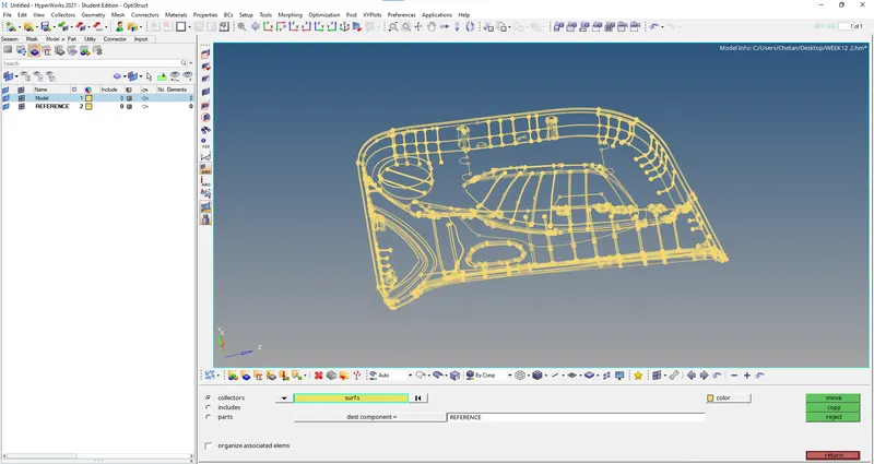
fig 1.5
* The criteria file setting is updated as per as the mentioned in the task, The values are updated and set as mentioned as shown in fig 1.6.
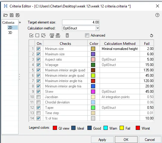
fig 1.6
*The mid surface is extracted for side door inner panel the component by using skin offset as shown in fig 1.7.
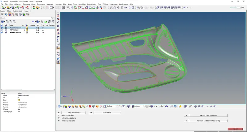
fig 1.7
* The Missing surface is created by using offset from parent component by selecting the surfaces with similar thickness individually as shown in fig 1.8.
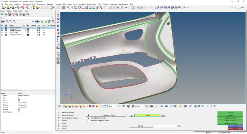
fig1.8
* The surface are overlapped in the region so by using the surface edit by trimming the surfaces with line the surface can be deleted as shown in fig 1.9.
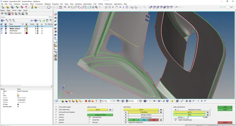
fig 1.9.
* For no accessible region the mash option is used and the entities are selected as shown in fig 1.10
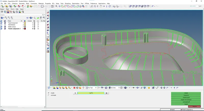
fig 1.10.
* By using the translate tool we can move the surface in required direction of the offseted surface for Connectivity as shown in fig 1.11.
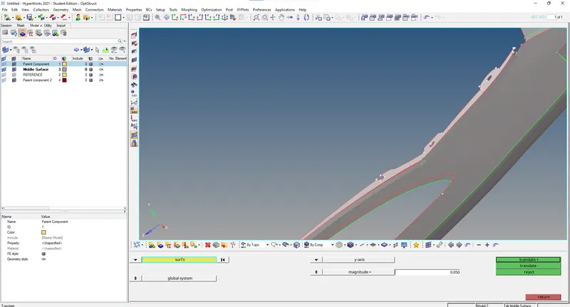
fig 1.11.
* The surface are overlapped in the region so by using the surface edit by trimming the intersecting surfaces the surface can be deleted as shown in fig 1.12.
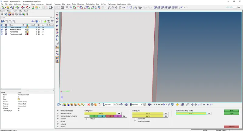
fig 1.12
* After the completion of the offset of the rib regions the surface must be extent to the mid surface using extent option from surface edit tool ,once the surface line turn yellow then it represents the t connection as shown in fig 1.13.
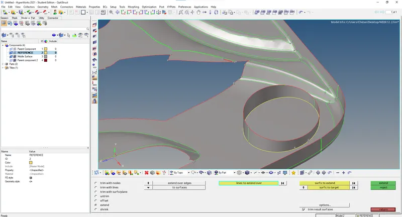
fig 1.13
* With the use of offset the rib feature mid surface is extracted and can be done by duplicating it to the mid surface component by making it current component as shown in fig 1.14
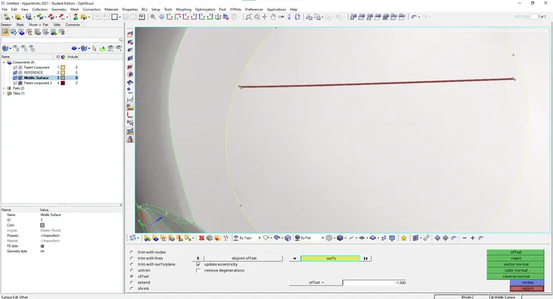
fig 1.14
* By using the translate tool we can move the surface in required direction of the offseted surface for Connectivity as shown in fig 1.15.
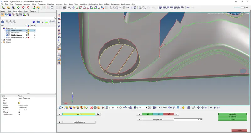
fig1.15
* After the completion of the offset of the rib regions the surface must be extent to the mid surface using extent option from surface edit tool ,once the surface line turn yellow then it represents the t connection as shown in fig 1.16.
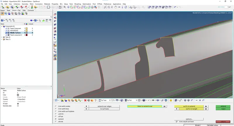
fig 1.16
* Same process is repeated after the completion of the offset of the rib regions the surface must be extent to the mid surface using extent option from surface edit tool ,once the surface line turn yellow then it represents the t connection as shown in fig 1.17.
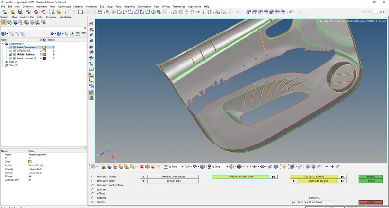
fig1.17
*The Side door inner panel’s mid surface geometrical clean-up is done by toggle line of unwanted lines and regions as shown in fig 1.18
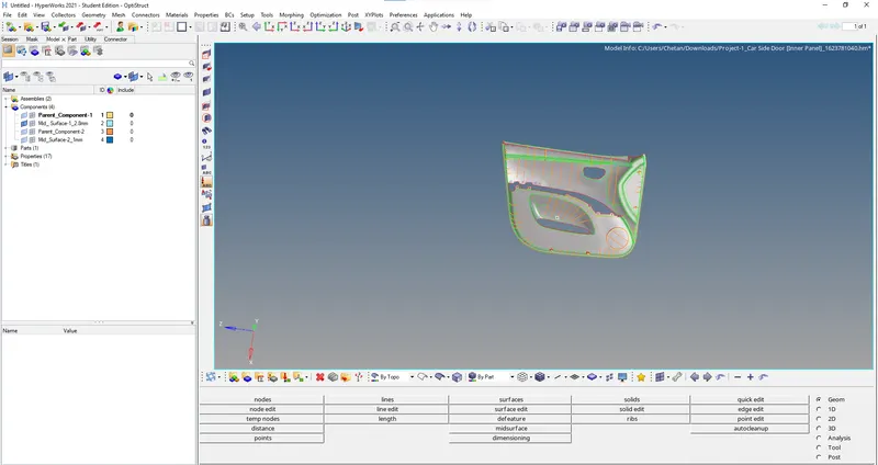
fig 1.18
*The meshing is done by selecting surfaces individually so the mesh would be uniform and good mesh flow as shown in fig 1.19.
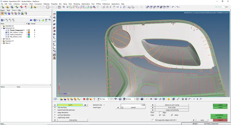
fig1.19
*The trias and failed elements can be fixed by using rebuild mesh by selecting the right areas with a defined geometry as shown in fig 1.20.
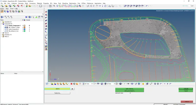
fig 1.20
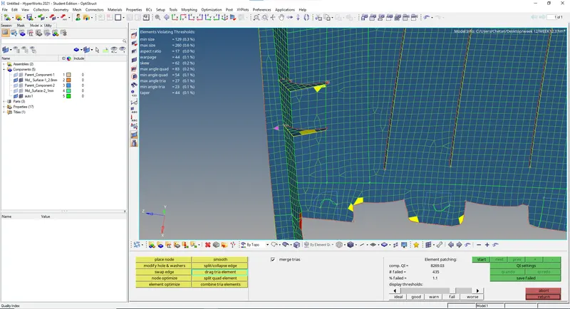
*By using quality index, the trias elements are dragged out the component in their direction as shown in fig 1.21.
 '
'
fig 1.21
*After dragging the tria element the elements are selected in defined geometry and smooth operation is used by keep nodes on geometry edges and smooth is done as shown in fig 1.22.
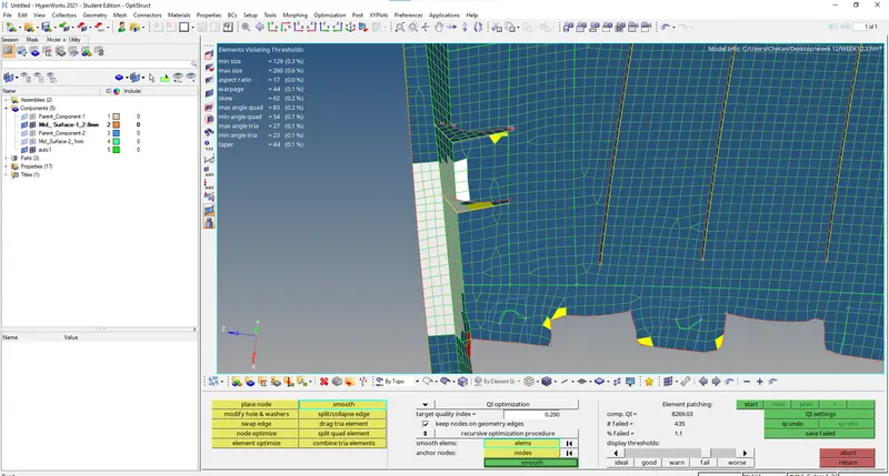
fig1.22
*Failed elements are selected and smooth operation is used to fix the issue, element optimize is also used as shown in fig 1.23.
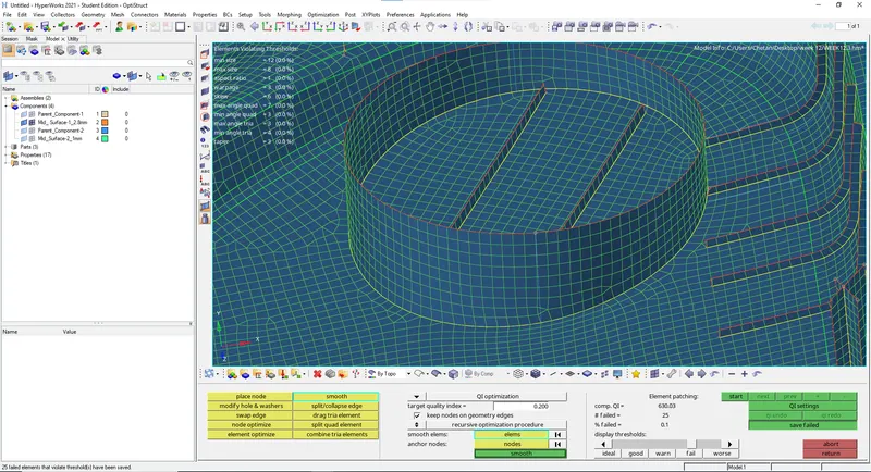
fig 1.23
*The elements failing for quality criteria the elements can be saved from quality index and save failed by using mask option the elements failed can be retrieved and fix the failed elements as shown in fig 1.24.
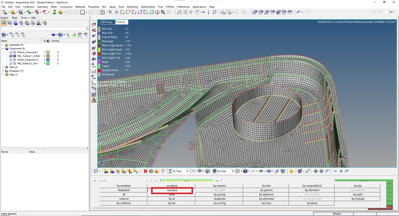
fig1.24
*The Distance tool used to measure the the rib thickness from the Parent component and properties are created as shown in fig 1.25.
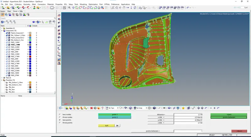
fig 1.25
*Creating the Property and in the property cards defining the thickness value for the ribs ,and creation of seperate components as per their thickness,Elements are selected by face as shown in fig 1.26.
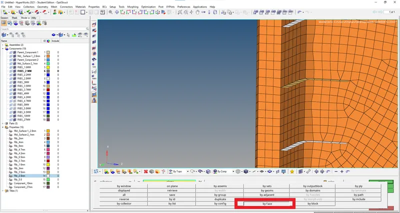
fig 1.26
*By using organise tool the rib section elements are moved to a different collector with suitable thickness values as shown in fig 1.27.
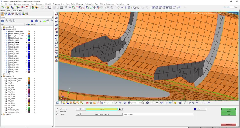
fig 1.27
*The overall tria percentage was checked the value was 1.3 % and no elements were failing for quality criteria as shown in fig 1.28.
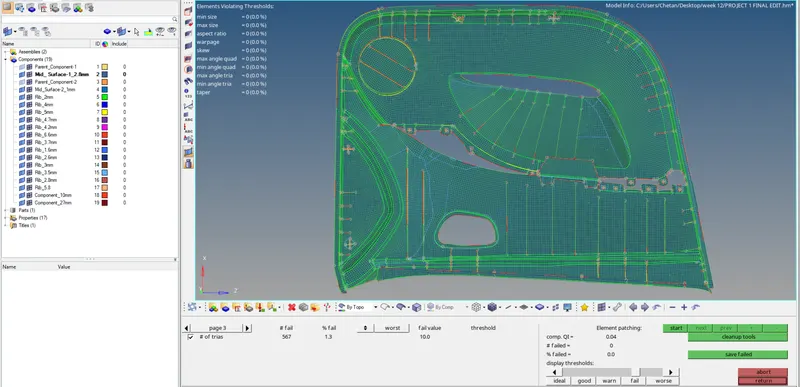
fig1.28
* Individualy selecting the Side door inner panel components and assigning the material and propertydetails as shown in fig 1.29.
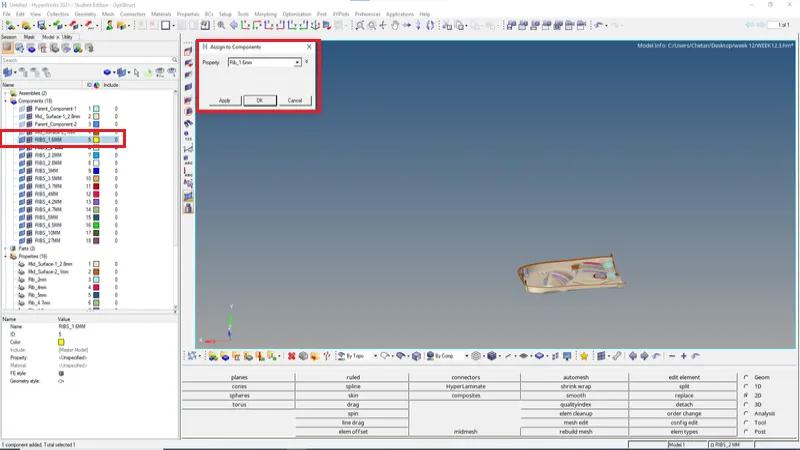
fig 1.29
* By using the 2D Detailed element repesentation we can view the different cross sectional elements in assigned thickness, this can be used as checker for and error due to updating the Element Type as shown in fig 1.30.
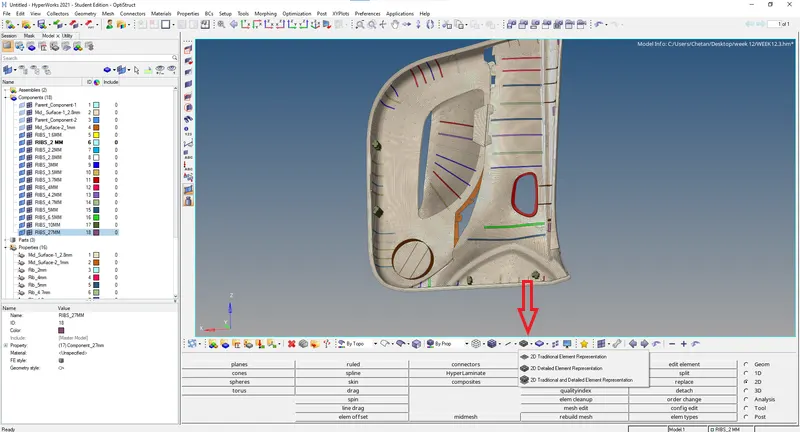
fig 1.30
*The free edges are checked if any openings or error in the surface by selecting all the components , red lines indicate the free edges as shown in fig 1.31.
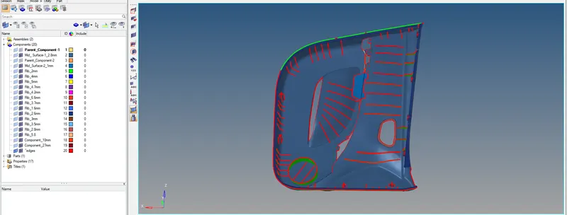
fig 1.31
*The T-Connections are checked if any free edge in the surface at intersections by selecting all the components,Yellow lines indicate the T-Connections as shown in fig 1.32.
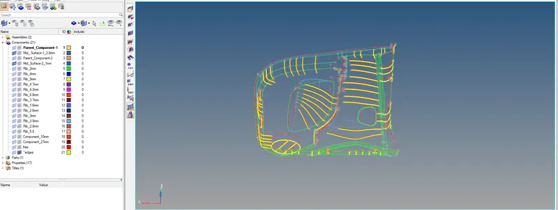
fig 1.32
*The below image is a combination of both free edges and T-Connections in the rib section of the components as shown in fig 1.33.
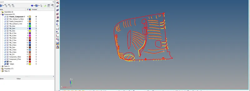
fig 1.33
*The below image is a combination of both for Checking the normals so the direction of the mid-surfaces are uniform of the Side door inner panel components as shown in fig 1.34.
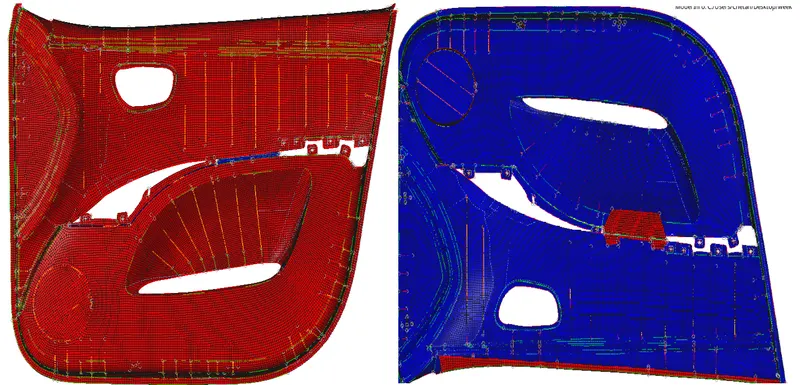
fig 1.34
*The final model is achived as per as the specified the Side door inner panel components are positioned in Front view as shown in fig 1.35.
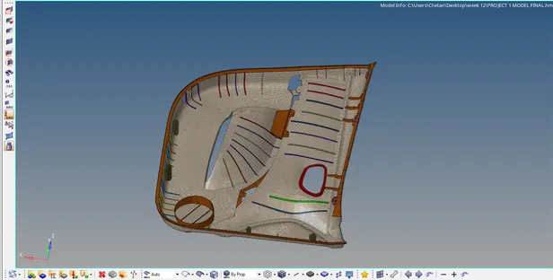
fig1.35
*The final model is achived as per as the specified the Side door inner panel components are positioned in Side view as shown in fig 1.36.
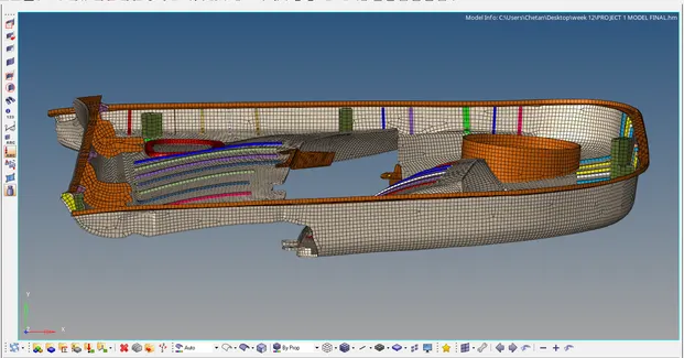
fig 1.36
*The final model is achived as per as the specified the Side door inner panel components are positioned in Isometric view as shown in fig 1.37.
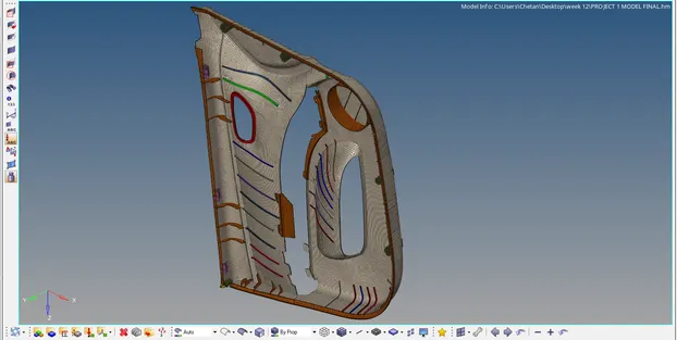
fig 1.37
RESULT:- The Side door inner panel model has been extraction of mid surface to mesh the model with overall tria percentage is been found to be 1.3% and the components are not failing for quality criteria. The free edges , T connection and Normals were checked with assigning property to the component represented in Front,Side and Isometric views.