Week 4-1D Element Creation Challenge
AIM :- To Mesh the Given component with the Size of 5 Units. Create 1D elements on the component with given cross-section and DOF.
OBJECTIVE:-
- Importing the model and creating a mid surface.
- Creating a mesh and refining the mesh and checking for amy unmeshed region or elements.
- Allocation of properties and material to the bracket.
- Creating RBE2 elements on hole A,D,E with specified Constrain DOF.
- Creating RBE3 Elements on Hole B,C with specified Constrain DOF.
- Creating a ROD element at Hole A, BEAM Element at Hole B and a BAR Element at Hole C.
- Creating a HYPERBEAM elements of a Box with Thin walls,Beam with Standard I Section and Cross Section bar.
- Allocate the Dimentions of the hyperbeam elements as specified.
- Update the elements as mention in order to achive the final output.
- Add the masses in Hole D and E.Spring elements at the end of the bracket to connect to each other .
- View the final representation with the bracket thickness and rod, beam and bar elements.
PROCEDURE:-
* The model is downloaded and imported by using geometric (IGES) file type to the work area as shown in fig1.1 .
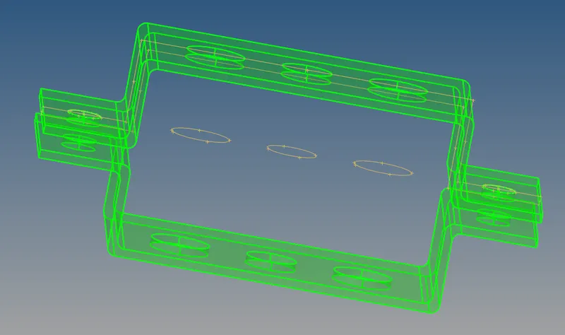
fig1.1
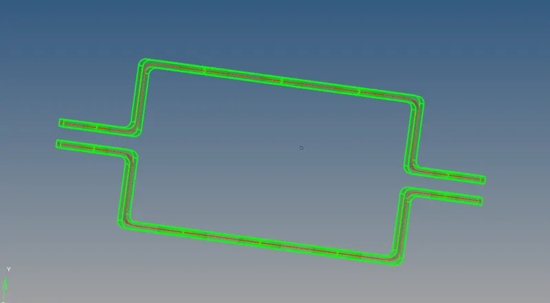
* The bracket is selected and the midsurface option is used and displayed surface is seleted and mid surface is formed as shown in Fig 1.2.The barcket is hidden and only the midsurface is isolated for the next step.
* The midsurface is prepared for mesh using washer split on all the holes on both the brackets and automesh is done by selecting the mesh size to be 5 .Checking for unmeshed elements is also done . Refine of the mesh is also done the inceasing the number of nodes near the holes and the fillet regions as shown in fig 1.3 .
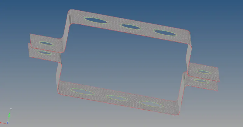
fig 1.3
*The properties of the bracket is adeed by creating it and the thickness of the bracket is specifed as 5mm.The Rod,Beam,Bar properties are also added with material specified as steel and assigned to the bracket as shown in fig 1.4 .
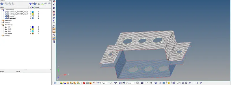
fig 1.4
*Creation of Rigids(RBE2) is done on circumference on the hole A on both the Brackets with constraining all translational DOF's as shown in fig1.5 .
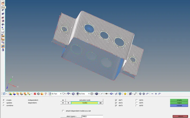
fig 1.5
* Creation of Rod is done on point where all the RBE2 elements converge at center on the hole A on both the Brackets node one is selected on top bracket and node two on bottom bracket as shown in fig1.6.
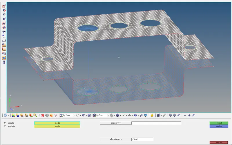
fig 1.6
* Creation of RBE3 is done on circumference on the hole B on both the Brackets with constraining all DOF's as shown in fig1.7 .
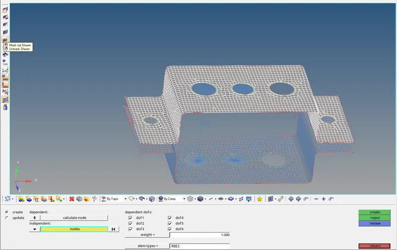
fig 1.7
* Creation of Beam is done on point where all the RBE3 elements converge at center on the hole B on both the Brackets node one is selected on top bracket and node two on bottom bracket and N1 and N2 is selected on botton bracket as shown in fig 1.8.
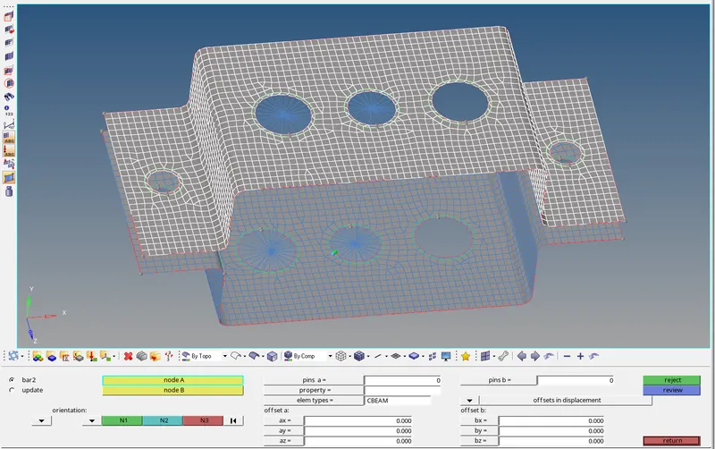
fig1.8
* Creation of RBE3 is done on circumference on the hole C on both the Brackets with constraining all DOF's in X and Y directions as shown in fig1.9.
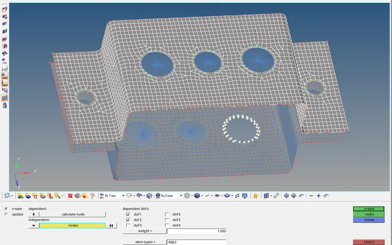
fig1.9
* Creation of Bar is done on point where all the RBE3 elements converge at center on the hole C on both the Brackets node one is selected on top bracket and node two on bottom bracket and N1 and N2 is selected on botton bracket as shown in 1.10.
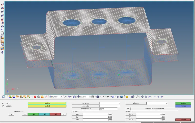
fig1.10
* Creation of Rigids(RBE2) is done on circumference on the hole D and E on both the Brackets with constraining all DOF's as shown in fig1.11.
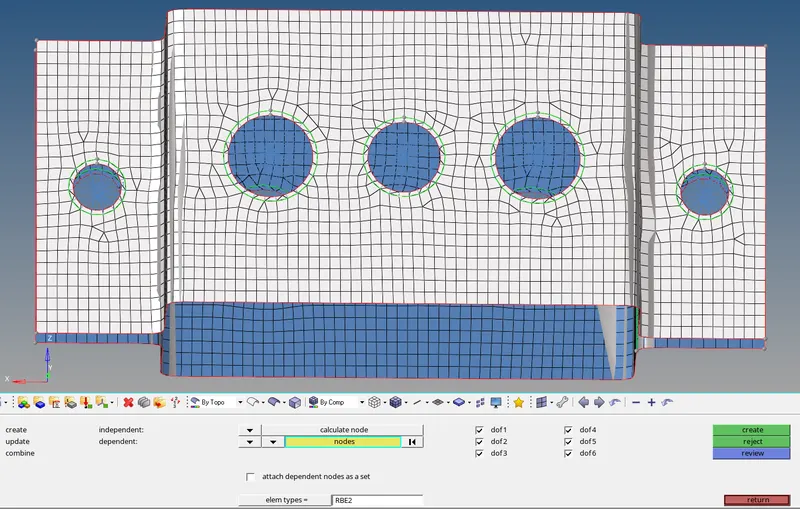
fig 1.11
* Creation of Masses is done on point where all the RBE2 elements converge at center on the hole Dand E on both the Brackets node one is selected on top bracket and node two on bottom bracket with a magnitude of 10 as shown in fig1.12.
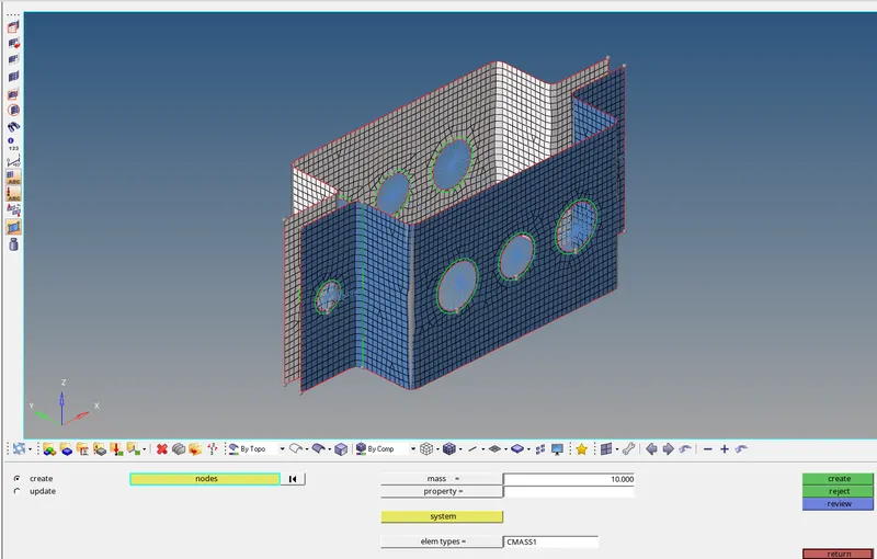
fig1.12
* Creation of Spring on the edge of the bothside and both the brackets by selecting the atleast 5 nodes on the each bracket as ashown in fig 1.13
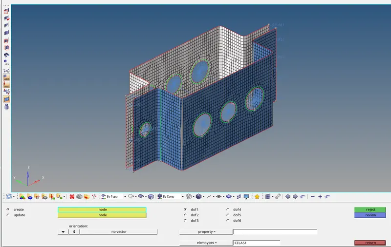
fig 1.13
* Creation of the HYPERBEAM elements and specifing the element type as Thin walled box and allocateing the dimention as specified repearting the same to standard I section and Cross section Bar as shown in fig 1.14.
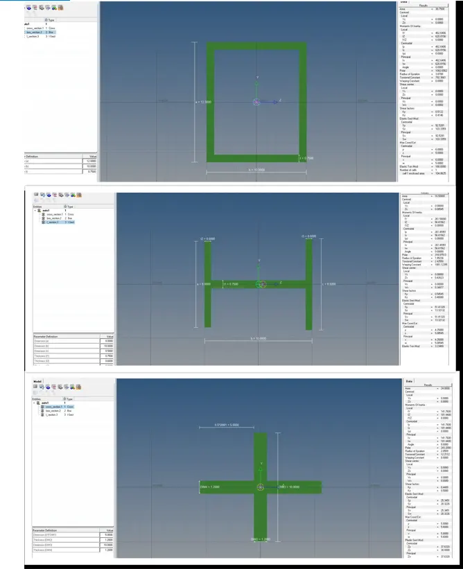
fig no 1.14
*Once hyperbeam is done the properties are add for rod, beam and bar element ,by going to the bar and rod option we can update the entites and futher carring out for each type of elements as specificed as shown in fig 1.15.
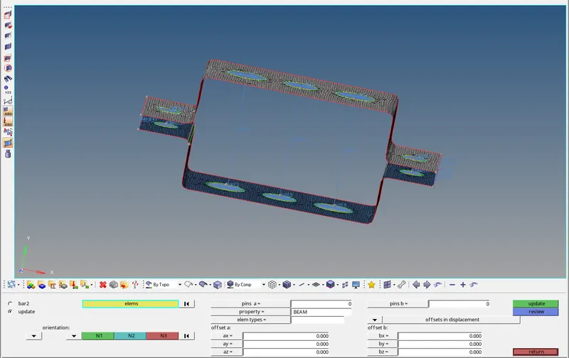
Fig 1.15
* By using the 1D Detailed element repesentation we can view the different cross sectional elements in a 3D aspect, this can be used as checker for and error due to updating the Element Type as shown in fig 1.16
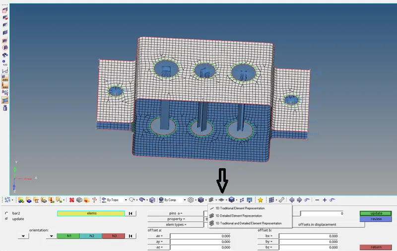
fig1.16
*The final model is represented by showing the actual bracket and the elements,mass added on the both the brackets as shown in fig no 1.17
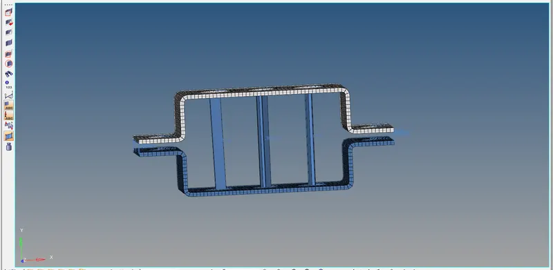
fig 1.17
*The final model is rendered in terms as matreial and colour to differenciate the elements and other attributes as shown in fig 1.18
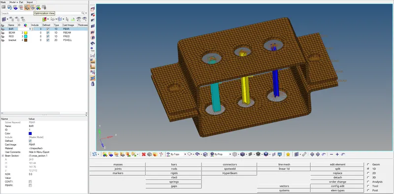
fig 1.18
RESULT:-The model is created and represented as specified dimentions and elements with masses and spring elements at the end of both the brackets.