Week 6-Meshing of Hood Challenge
AIM:- To import the hood model and performing geometry clean up and extraction of mid surface to mesh the model.
OBJECTIVE:-
- To import the hood model .
- Creating a quality criteria parameters as instructed.
- Deleting the solids on the model components.
- Extraction of mid surface for all components separately.
- Performing geometry clean up and definition of the structure of the components.
- Creating section of the components into mesh region.
- Check for trias and rotational quards .
- Elimination of trias by rebuild mesh and automesh.
- Performing quality criteria opertion drag trais out and smoothing the dragged area.
- Check for element quality criteria and fix them by projecting for warpage,nodal and element for skew ,min and Max length.
- For inner and outer hood extract the meshing is done by reflect the symmetrical surface.
- Check for free egdes and equivalence before reflect.
- For outer hood extract at the hemming region the mid line is concerned so the elements does not fail for size .
- The element quality check is done for all components ,duplicate is checked and deleted .
PROCEDURE:-
*The import of the model is been done by Model and creating seperate components for the hood components as shown in fig1.1a , 1.1 b ,1.1 c .
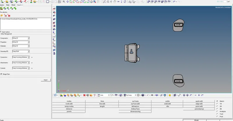
fig1.1a
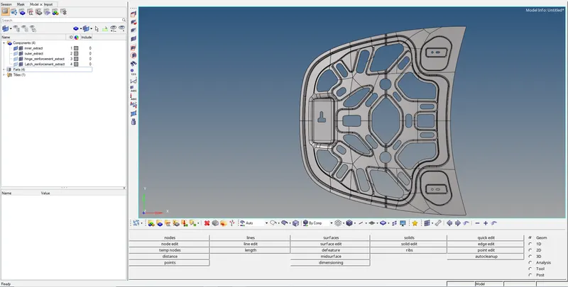
fig1.1b
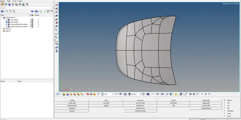
fig1.1c
* The criteria file setting is updated as per as the mentioned in the task, The values are updated and set as mentioned as shown in fig 1.2a and 1.2b.
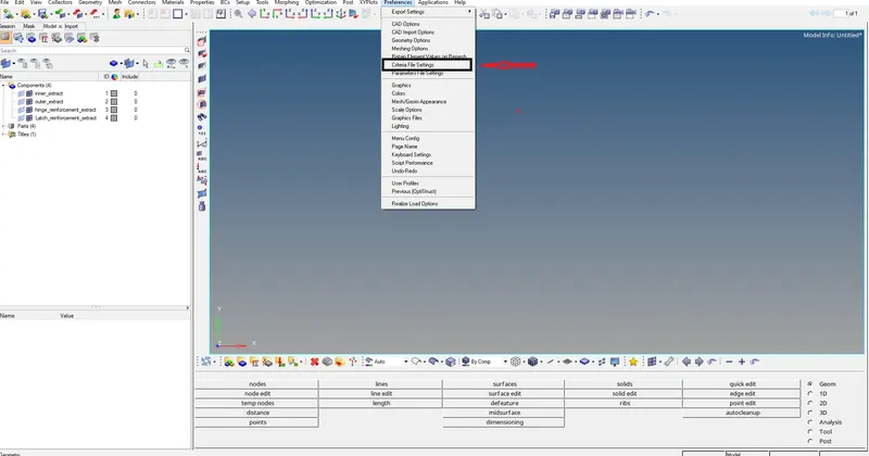
fig 1.2a
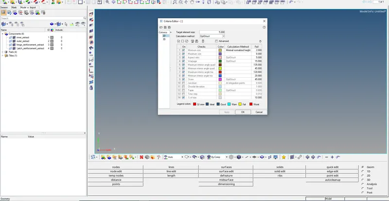
fig1.2b
*The components are selected and deletions for the solid are deleted as shown in fig 1.3.
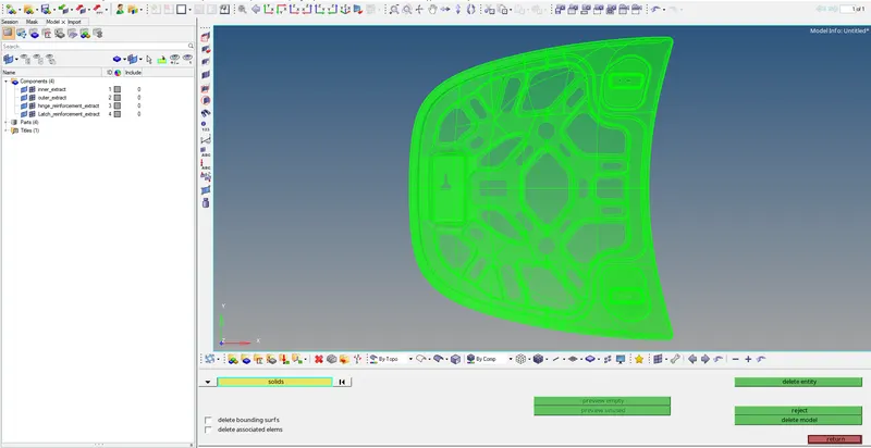
fig 1.3
*The mid surface is extracted for hood inner the component by using skin offset as shown in fig 1.4a and 1.4 b.
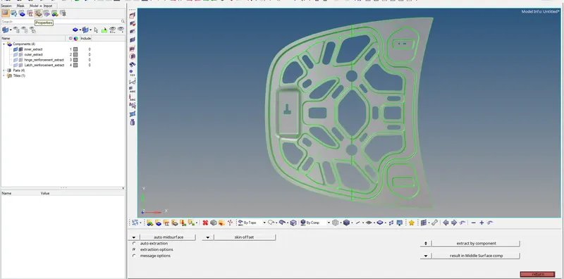
fig 1.4a
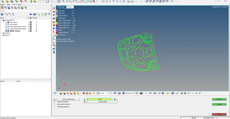
fig 1.4 b
*The mid surface is extracted for hood outer the component by using skin offset as shown in fig 1.5a and 1.5b.
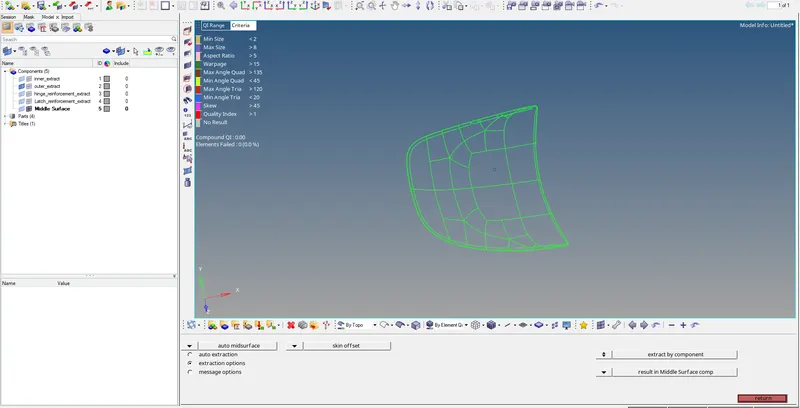
fig 1.5a
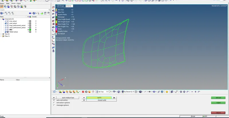
fig1.5b
*The mid surface is extracted for hinge reinforcement the component by using skin offset as shown in fig 1.6.
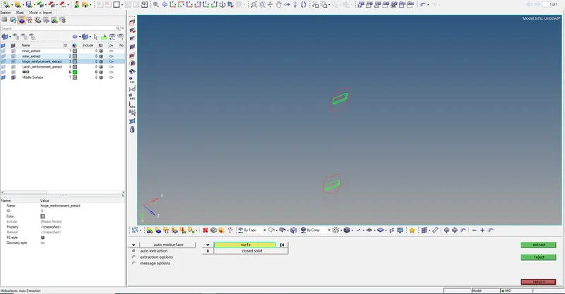
fig 1.6
*The mid surface is extracted for latch reinforcement the component by using skin offset as shown in fig 1.7.
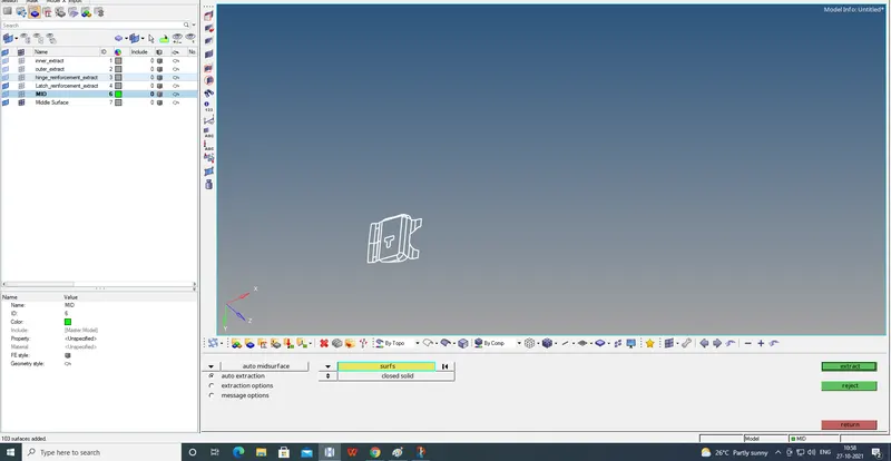
fig 1.7
*The latch reinforcement mid surface geometrical cleanup is done by toggle line of unwanted lines and regions as shown in fig 1.8.
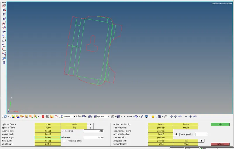
fig 1.8
*The meshing is done by selecting surfaces individually so the mesh would be uniform and good mesh flow as shown in fig 1.9a and 1.9b.
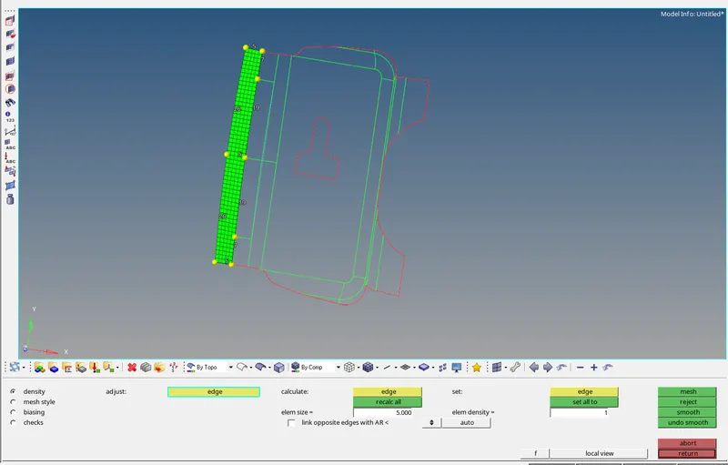
fig 1.9a
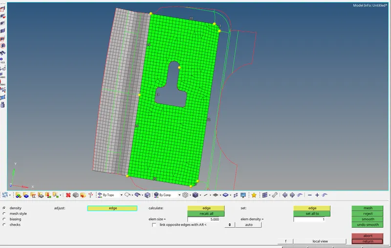
fig 1.9b
*By using quality index the trias elements are dragged out the component in there direction as shown in fig 1.10.
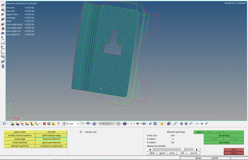
fig 1.10
*After dragging the tria element the elements are selected in defined geometry and smooth operation is used by keep nodes on geometry edges and smooth is done as shown in fig 1.11.
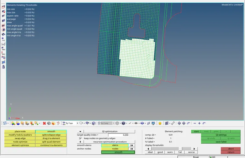
fig 1.11
*In fillet and conture regions the elements tend to fail the quality criteria by using the quality index the elements can be fixed as shown in fig 1.12.
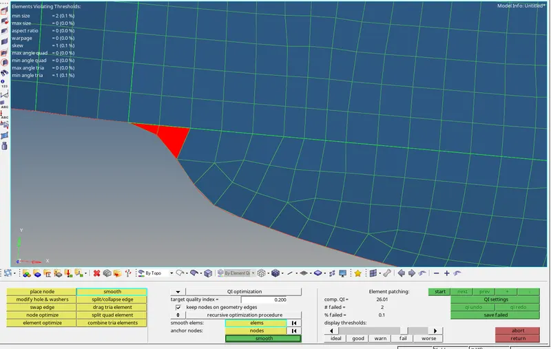
fig 1.12
*The hinge reinforcement mid surface geometrical cleanup is done by toggle line of unwanted lines and regions as shown in fig 1.13.
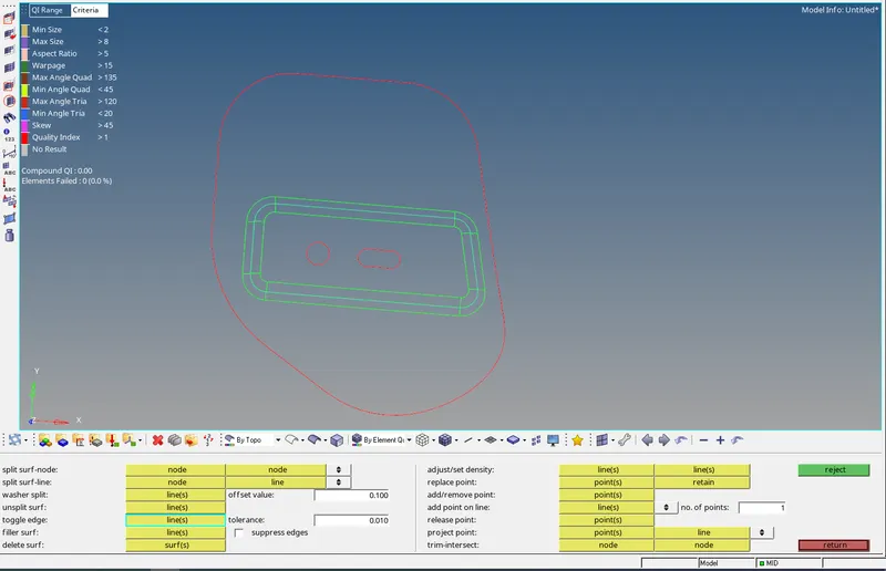
fig 1.13
*The meshing is done by selecting surfaces individually so the mesh would be uniform and good mesh flow as shown in fig 1.14.
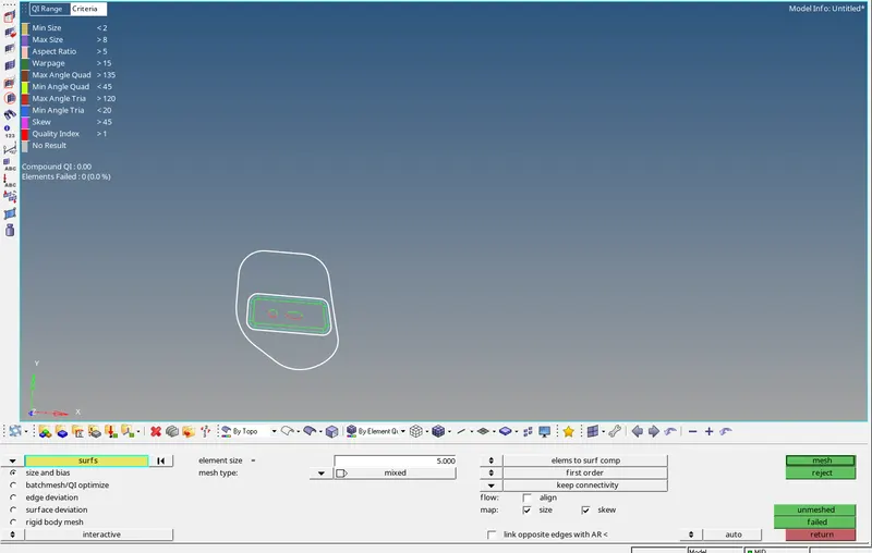
fig 1.14
*The trias and failed elements can be fixed by using rebuild mesh by selecting the right areas with a defined geometry as shown in fig 1.15.
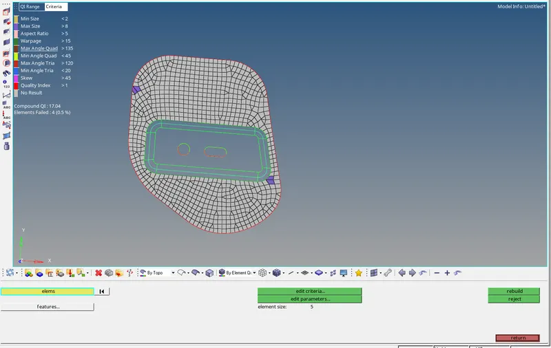
fig 1.15
*The hood outer mid surface is a symmetrical component so the component is split into two parts and deleted the one side of the surface by delete operation as shown in fig 1.16
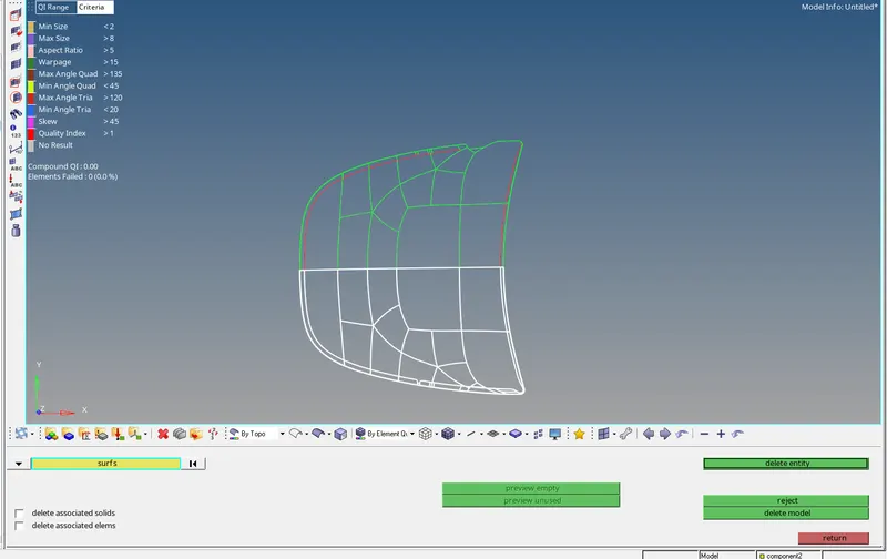
fig 1.16
*The geometry cleanup is done by using toggle line for unwanted lines and regions since this surface consists of a hemming region so the midline is created and others are toggled as shown in fig 1.17a and 1.17b .
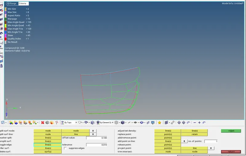
fig 1.17a
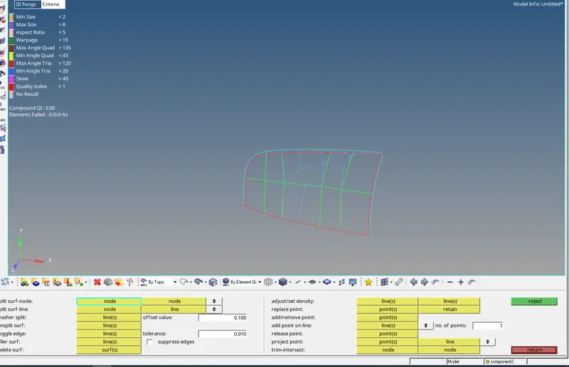
fig1.17b
*The meshing is done by automesh and selecting surfaces individually so the mesh would be uniform and good mesh flow for elimination of trias rebuild mesh is done as shown in fig 1.18.
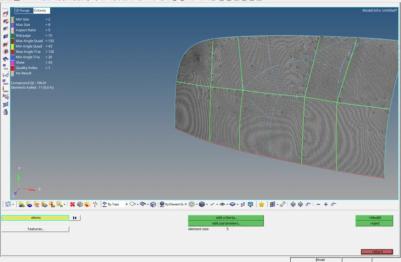
fig 1.18
*The elements failing for quality criteria the elements can be saved from quality index and save failed as shown in fig 1.19.
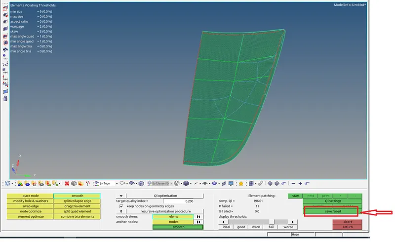
fig 1.19
*By using mask option the elements failed can be retrieved and fix the failed elements as shown in fig 1.20.
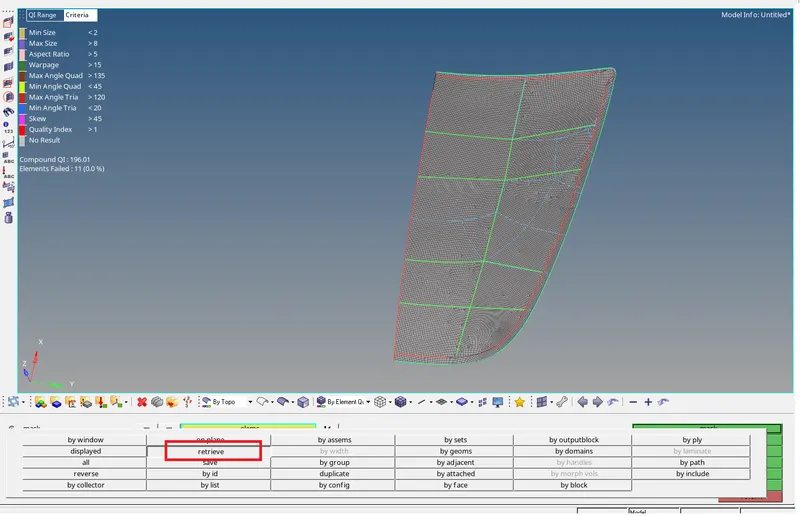
fig 1.20
*Failed elements are selected and smooth operation is used to fix the issue , element optimize is also used as shown in fig 1.21.
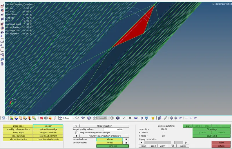
fig 1.21
*The free edges are checked before reflect the surface to the other side and equivalence is also checked as shown in fig 1.22.
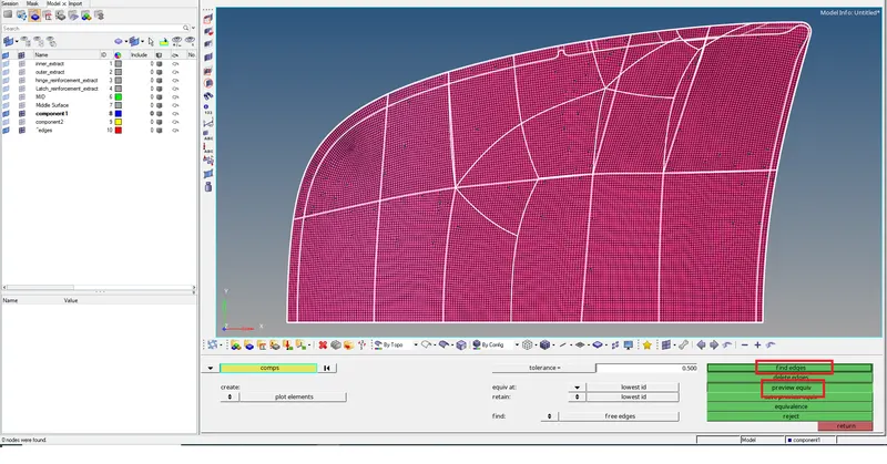
fig 1.22
*The surface is reflect by selecting the surface and duplicate the current component and selecting the base point and axis of reflect as shown in fig 1.23a and 1.23b.
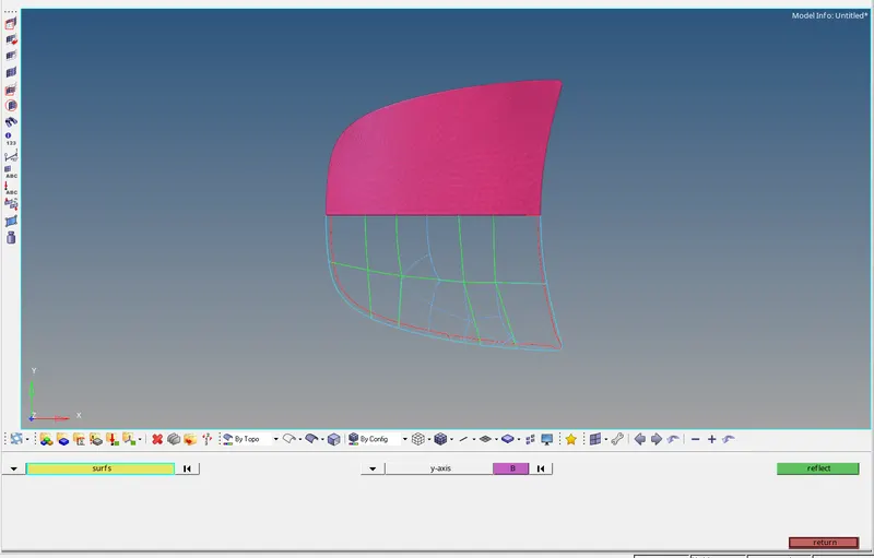
fig 1.23a
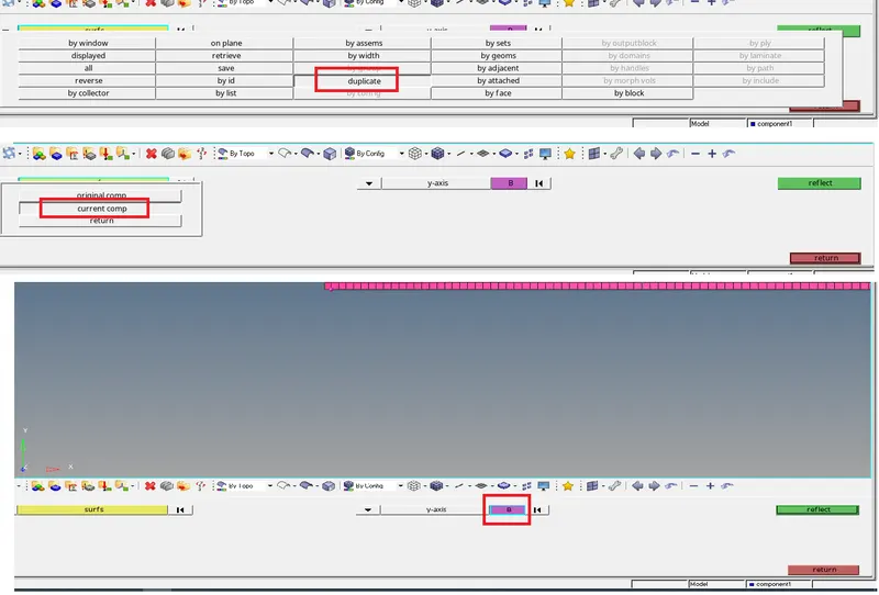
fig 1.23b
*The mesh is also reflect the say as surface but the selection is elements duplicate in current component and selecting the axis and base point as shown in fig 1.24.
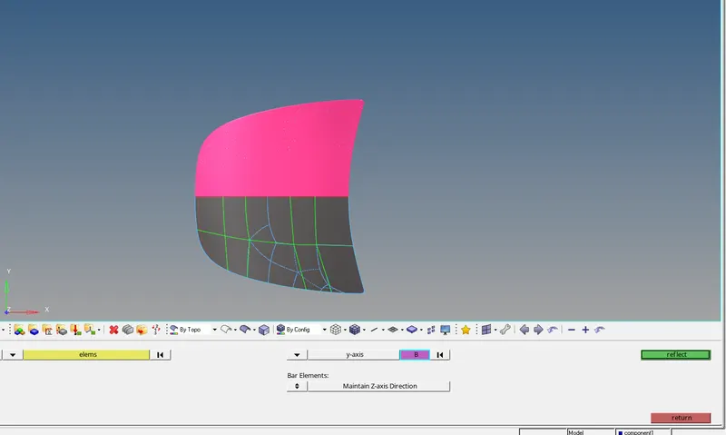
fig 1.24
*The free edges are checked after reflect the mesh to the other side and equivalence is also checked and rectified to create a steady mesh flow as shown in fig 1.25.
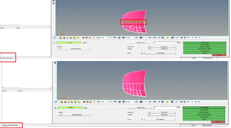
fig 1.25
* By using translate option the warpage in the element is removed this works under only 10 degree of excess, the nodes are selected and a magnitude of 0.1 is used as shown in fig 1.26.
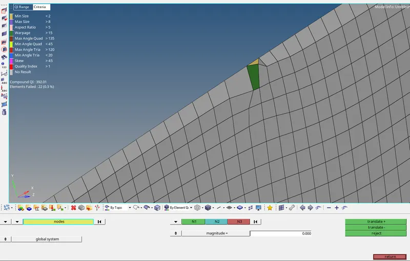
fig 1.26
*The minimun length fail is rectified by using distance option and by selecting the node the dimention is changed with out harming the geometry as shown in fig 1.27.
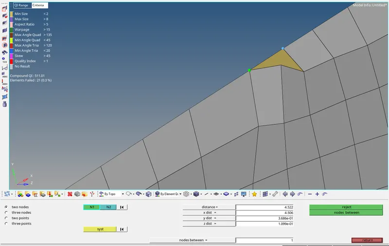
fig 1.27
*The components are checked for quality criteria and there are no failed elements as shown in fig 1.28.
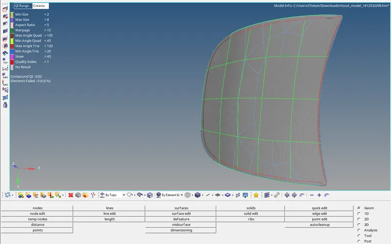
fig 1.28
*The geometry cleanup is done by using toggle line for unwanted lines and regions since this surface consists of conture regions and inner line are made so the fillet and corners so the geomerty is retained and others are toggled as shown in fig 1.29a and 1.29b.
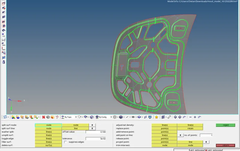
fig 1.29a
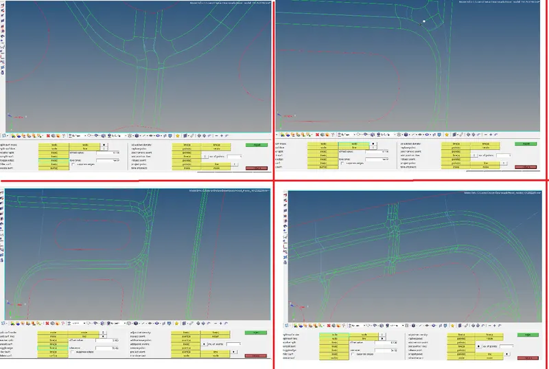
fig 1.29b
*The meshing is done by automesh and selecting surfaces individually so the mesh would be uniform and good mesh flow for elimination of trias rebuild mesh is doneFailed elements are selected and smooth operation is used to fix the issue , element optimize is also used as shown in fig 1.30a and 1.30b.
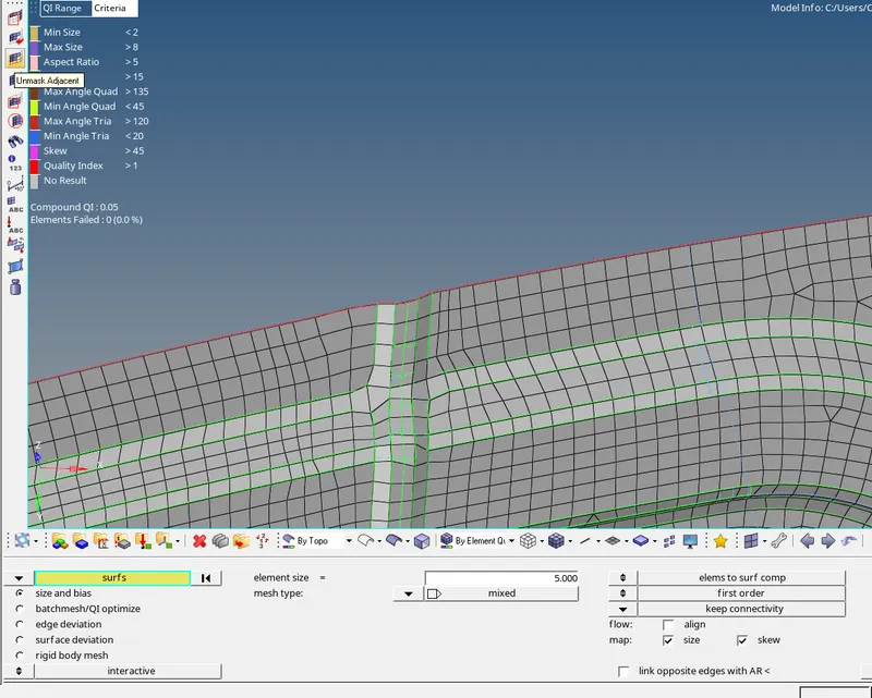
fig 1.30a
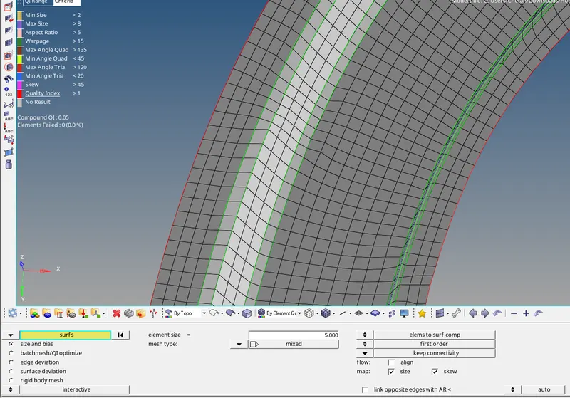
fig1.30b
* The overall tria percentage is been found to be 1.5 and the components are not failing for quality criteria as shown in fig 1.31.
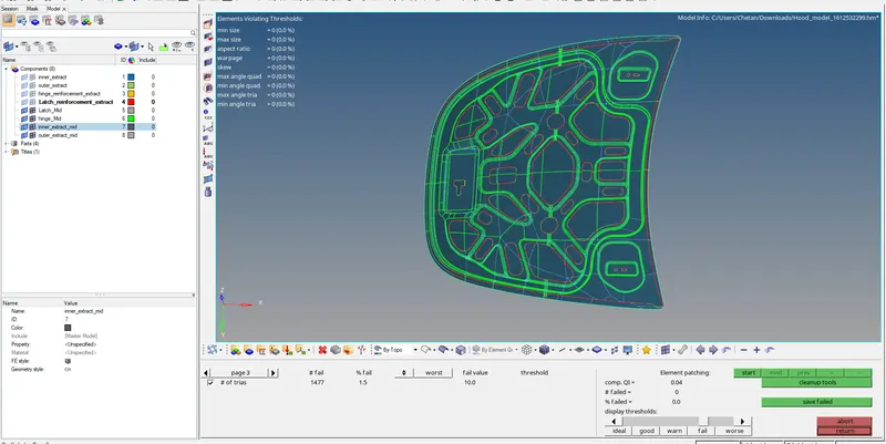
fig 1.31
RESULT:- The hood model is performing geometry clean up and extraction of mid surface to mesh the model and overall tria percentage is been found to be 1.5 and the components are not failing for quality criteria.