Week 8-3D Tetra Meshing Challenge
AIM:- To create tetramesh for the given components as specified size and mesh methods without any failed elements.
OBJECTIVE:-
- Importing the components.
- Deleting the solid for the housing component.
- Creating a quality criteria for housing component.
- Automesh the housing component with tria element of target size 5.
- Tetramesh the 2d elements into 3d elements.
- Check elements for failure in min and max size and tet collapse.
- Cleanup of geometry for component 2 and turbocharger assembly.
- By using the solid creating a volumetric tetra mesh of traget size 3 and 4 by using in 3d panel or utility tool.
- Check for tet collapse and fix it by tetra remesh .
- Fixing the tet collapse by using distance tool.
PROCEDURE:-
*The quality criteria file is created for the housing component for both 2d and 3d parameters as shown in fig 1.1.
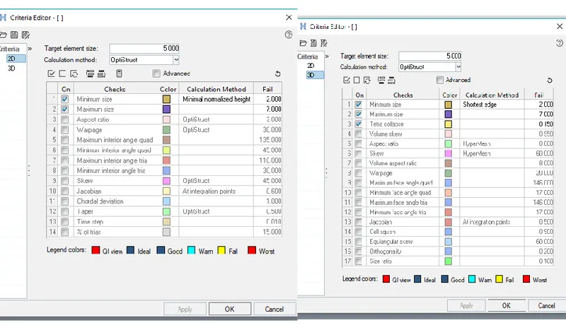
fig 1.1.
*The components are imported and separated housing and the flange as shown in fig 1.2
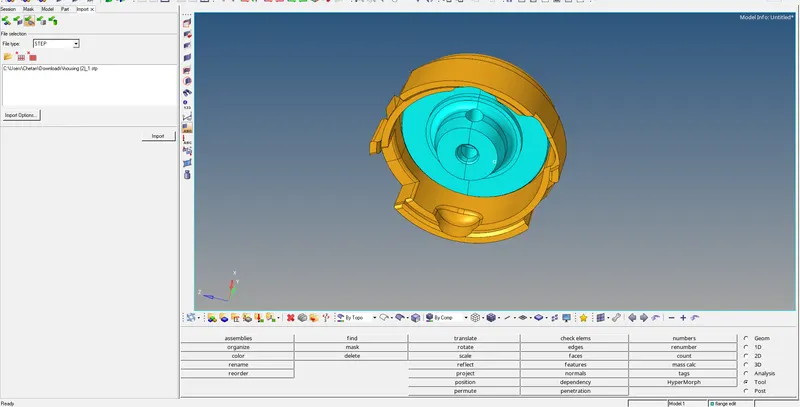
fig 1.2
*Deletions of the solid and Geometry cleanup is done on the surface of the component as shown in fig 1.3.
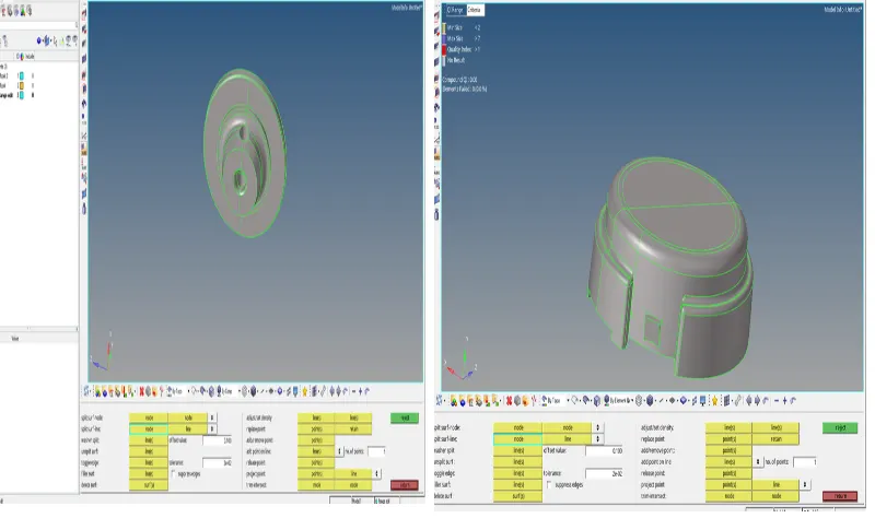
fig 1.3
*By using automesh tool creating a tria mesh with target size of 5 as shown in fig 1.4.
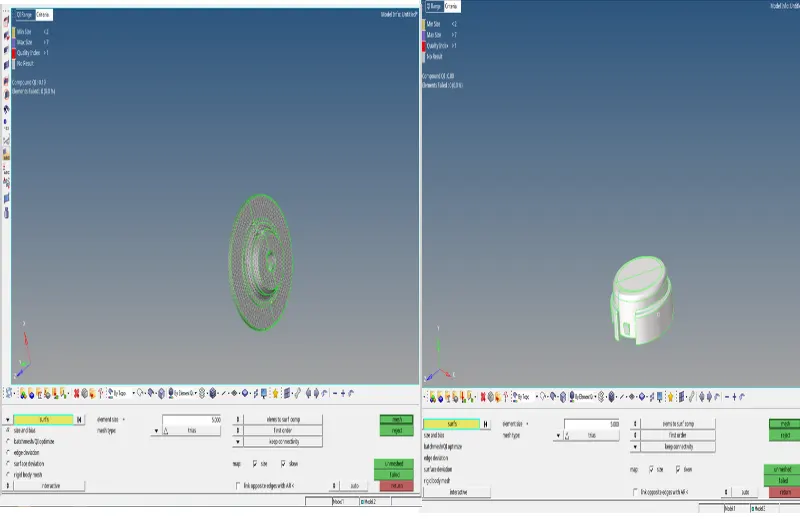
fig 1.4
*Using tetramesh tool to convert 2d elements into 3d elements as shown in fig 1.5.
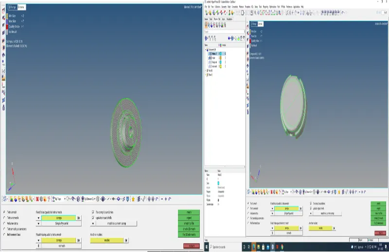
fig 1.5
*From the tetra parameters the parameters are alterated as required and tetra remesh is used to fix the failing elements as shown in fig1.6.
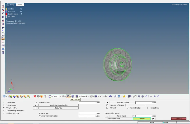
fig 1.6
*The elements are checked for both size and tet collapse as shown in fig 1.7
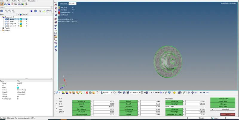
fig 1.7
*The component is displayed and solid is not delete so volume mesh can be done as shown in fig 1.8.
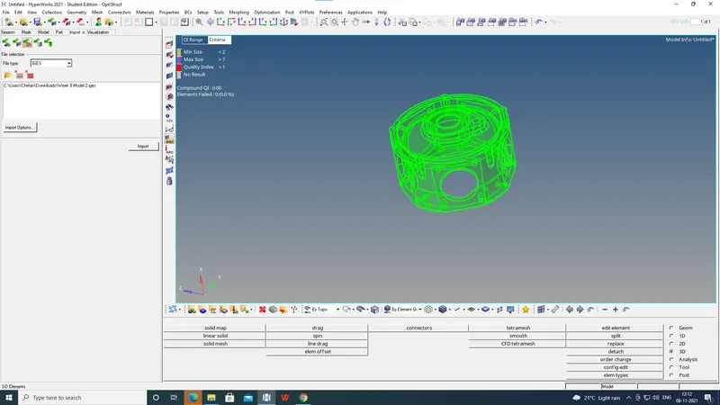
fig 1.8.
*For this component volume tetra is done so the component is geometry cleaned up for meshing as shown in fig1.9.
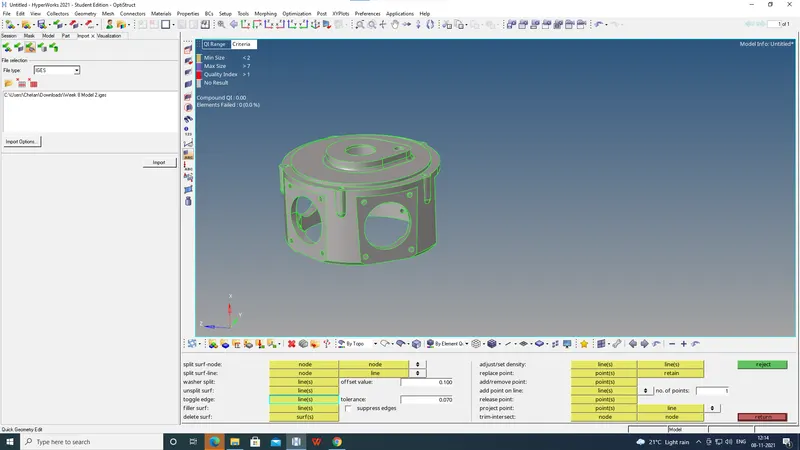
fig1.9.
*The component is selected and volume tetra is created,the 3d elements are created as shown in fig 1.10
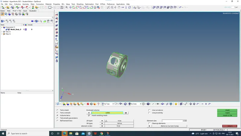
fig 1.10
*The elements are checked for tet collapse as shown in fig 1.11.
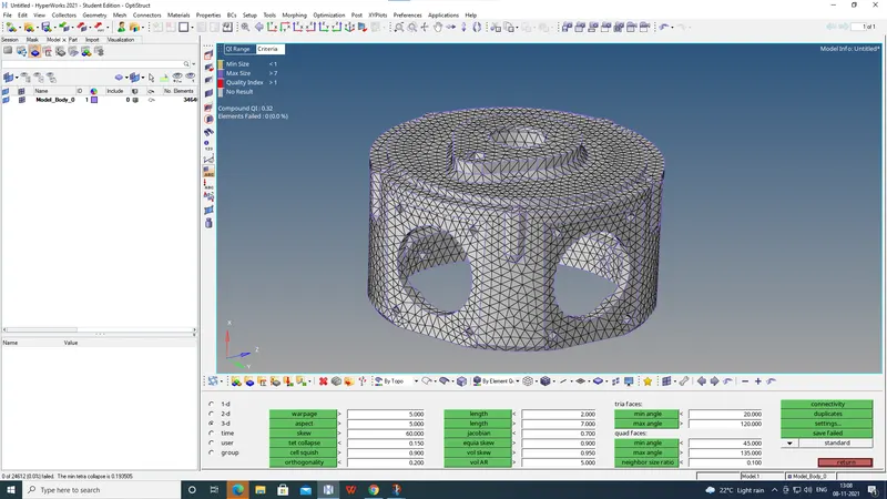
fig 1.11.
*The turbocharger assembly is imported and separated the casing and compressor wheels and body as shown in fig 1.12.
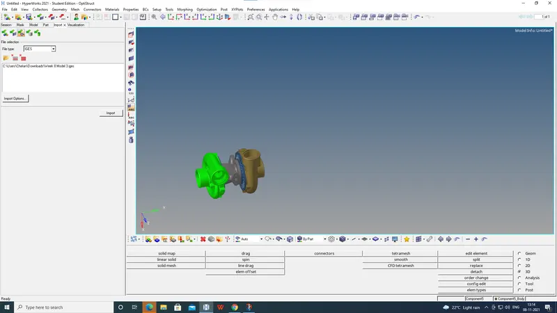
fig 1.12.
*Geometry cleanup is done for the casing 1 and volume tetra is created by using the solid as shown in fig 1.13.
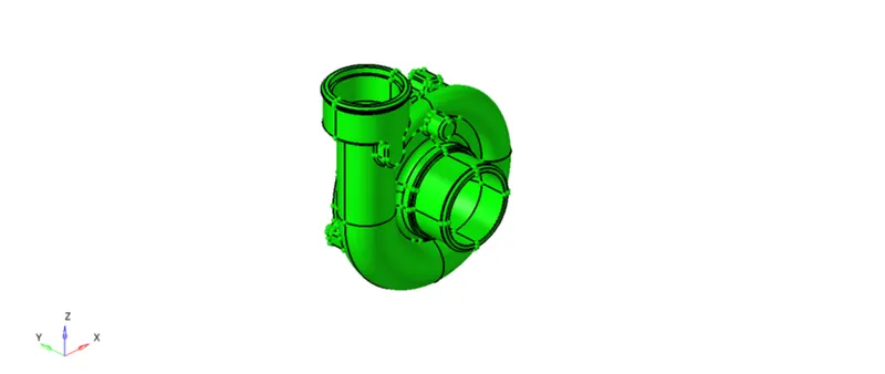
fig 1.13.
*The elements are selected and checked for 3d creation by using mask tool as shown in fig 1.14
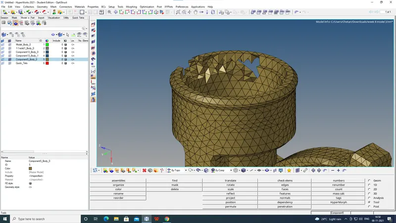
fig 1.14
*The elements are checked for tet collapse as shown in fig 1.15.
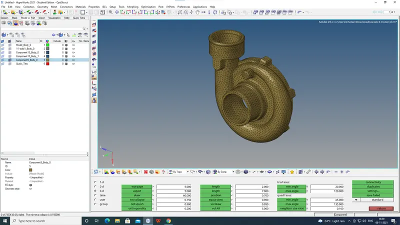
fig 1.15.
*The geometry cleanup is done on the body and unwanted lines are toggled as shown in fig1.16.
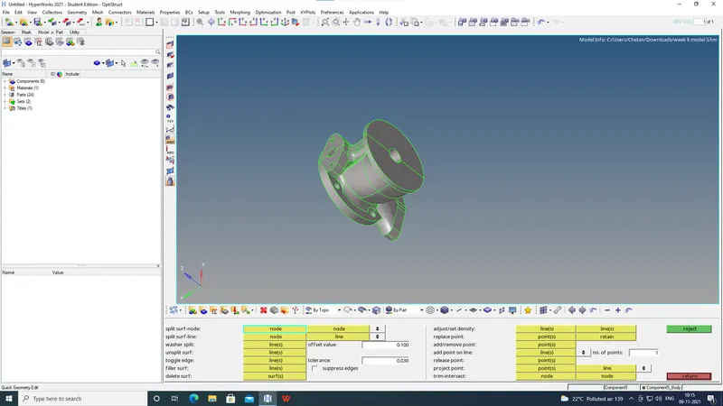
fig1.16.
*The solid is selected and volume tetra is been created by selecting the mesh size 4 as shown in fig 1.17.
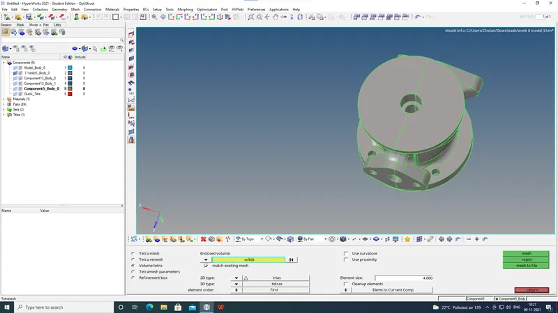
fig1.17.
*The elements are checked for tet collapse as shown in fig 1.18.
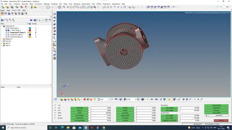
fig 1.18.
*The geometry cleanup is done on the Compressor wheel 1 and unwanted lines are toggled as shown in fig1.19.
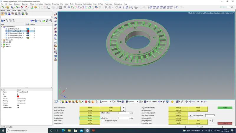
fig 1.19.
*The solid is selected and volume tetra is been created by selecting the mesh size 4 as shown in fig 1.20.
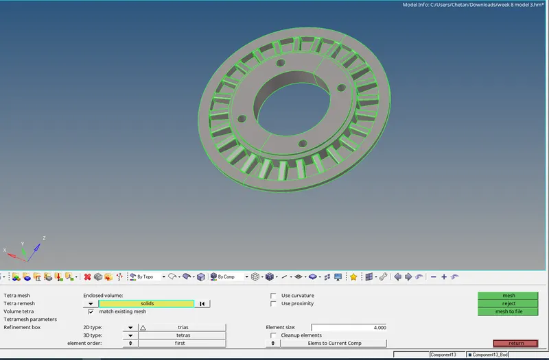
fig 1.20.
*The elements are checked for tet collapse as shown in fig 1.21.
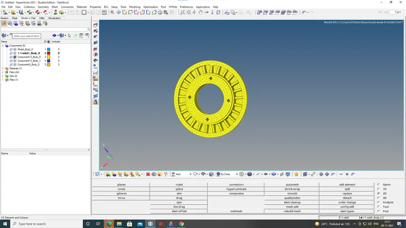
fig 1.21.
*The geometry cleanup is done on the Compressor wheel 2 and unwanted lines are toggled as shown in fig1.22.
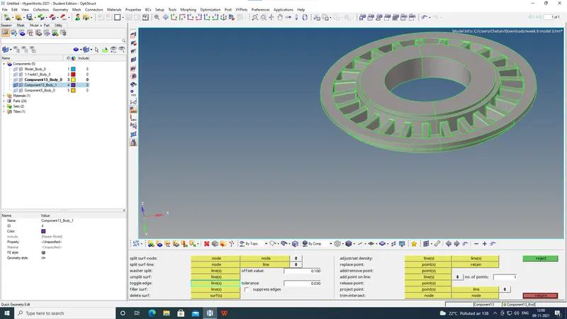
fig 1.22.
*The solid is selected and volume tetra is been created by selecting the mesh size 4 as shown in fig 1.23.
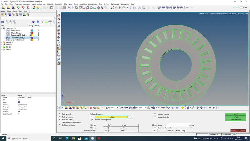
fig 1.23.
*The elements are checked for tet collapse as shown in fig 1.24.
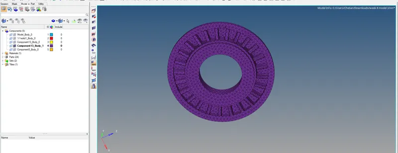
fig 1.24.
*The elements are checked for tet collapse and the failed elements are save as shown in fig 1.25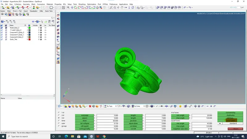
fig 1.25.
*By using the mask option the elements are retrieved and fixed by tetra remesh as shown in fig 1.26.
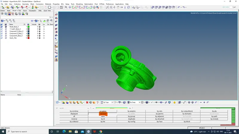
fig 1.26.
*The elements are checked for tet collapse as shown in fig 1.27.
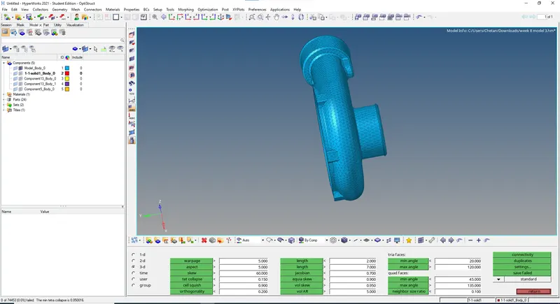
fig 1.27.
RESULT:- The given models are tetra meshed by tetramesh and volume tetra .The tet collapse was checked and no elements failed.