Week 9 - Parametric study on Gate valve.
AIM: To perform a Parametric study on the Gate valve.
OBJECTIVE:
- To perform a parametric study on the gate valve simulation by setting the opening from 10% to 80%.
- To obtain the mass flow rates at the outlet for each design point.
- To calculate the flow coefficient and flow factor for each opening and plot the graph.
THEORY:
Gate Valve:
Gate valves are valves that operate by lifting a round or rectangular gate out of the path of the fluid. This valve facilitates only unidirectional flow, but unlike globe valves, they give a full bore flow to the fluid. The round or wedge-shaped ring is known as a gate as it moves in a perpendicular direction to the flow of the fluid.
A gate valve controls the media's flow by lifting the gate (open) and lowering the gate (closed). A gate valve's distinct feature is the straight-through unobstructed passageway, which induces minimal pressure loss over the valve. The unobstructed bore of a gate valve also allows for a pig's passage in cleaning pipe procedures, unlike butterfly valves.
Flow Coefficient:
The flow coefficient of a device is a relative measure of its efficiency at allowing fluid flow. It describes the relationship between the pressure drop across an orifice valve or other assembly and the corresponding flow rate.
Mathematically the flow coefficient Cv (or flow-capacity rating of the valve) can be expressed as:
`K_v=Q*sqrt((SG)/(Delta P)) ((m^3)/(hr))`
where:
Q is the rate of flow (expressed in US gallons per minute).
SG is the specific gravity of the fluid (for water = 1)
`DeltaP` the pressure drop across the valve
In more practical terms, the flow coefficient is the volume (in US gallons) of water at `60^0 C` that will flow per minute through a valve with a pressure drop of 1 psi across the valve.
The use of the flow coefficient offers a standard method of comparing valve capacities and sizing valves for specific applications that are widely accepted by the industry. The general definition of the flow coefficient can be expanded into equations modeling the flow of liquids, gases, and steam using the discharge coefficient.
Flow Factor:
The metric equivalent flow factor (Kv; commonly used everywhere else in the world except the United States) is calculated using metric units:
`K_v=Q*sqrt((SG)/(Delta P)) ((m^3)/(hr))`
Where;
`K_v`is the flow factor (expressed in (m^3)/(hr))
Q is the flow rate (expressed in cubic meters per hour [(m^3)/(hr)]).
SG is the specific gravity of the fluid (for water = 1).
is the differential pressure across the device (expressed in [bar]).
`C_v` can be calculated from `K_v` using the equation:
Parametric study:
A parametric study is a study that influences design variables in the product design model to explore design alternatives that can effectively support the product concept designs. A parametric study is simple and easy to perform as long as the mapping between CAD and simulation models has been established.
The objective of this parametric study is to study the mass flow rate at the outlet of the gate valve during different levels of lift of the gate disc.
SOLUTION:
Here we will perform a parametric study on the gate valve simulation by setting the opening from 10% to 80%. With the help of the parametric option, for the lift of the gate disc, we can parametrize the lift and see the different results or changes with different lift percentages. Once we have 10% of the lift, we will parameterize the lift and perform the analysis. Then we will see the changes in contours and other variables like mass flow rate, flow coefficient, and flow factor for all results one by one respectively.
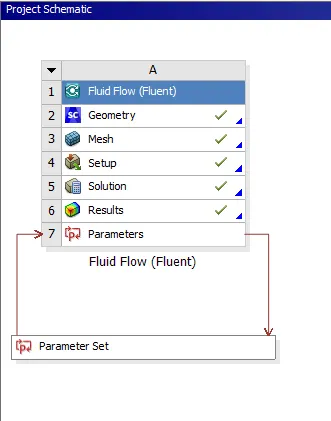
Project schematic:
PROCEDURE:-
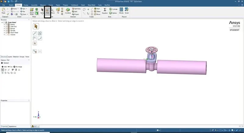
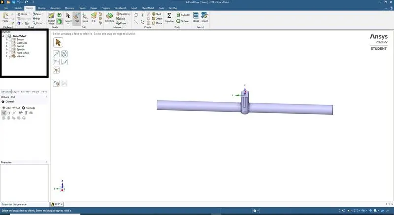
*The Gate Valve model is been imported to the SpaceClaim and the bottom part has been extended to 800 mm so the volume extraction will be easy.
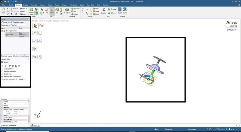
*The valve disc is moved in the y-direction by a value of 7.54 mm and the value is been parameterized so the gate valve simulation.
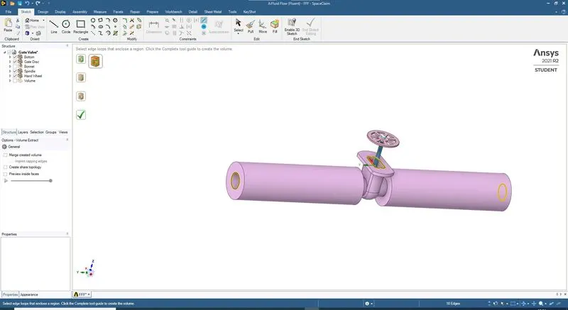
*The volume is been extracted for the gate valve. The model is suppressed for physics.
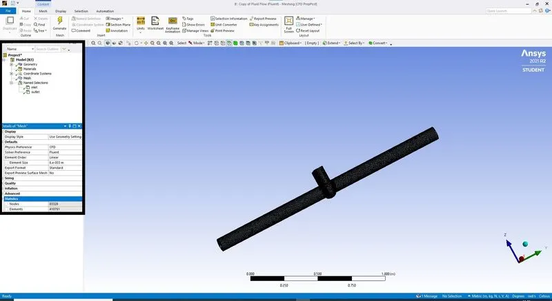
*The volume extracted is been meshed with a mesh size of 6 mm. The elements created are 410781
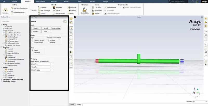
*The Setup workbench is started and given recommended parameters.
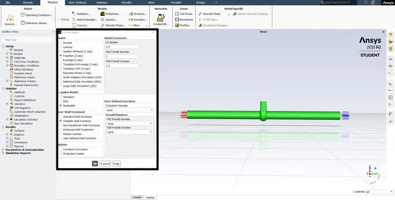
*The turbulent model is used with K epsilon model with realizable and Scalable wall function
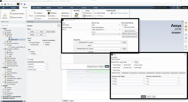
*The material is been added, the air is been initiated with specific values at and the fluid zone is been initiated as water.
*Boundary Conditions are applied on the inlet with Pressure values, outlet with pressure at zero.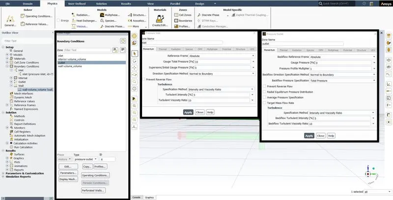
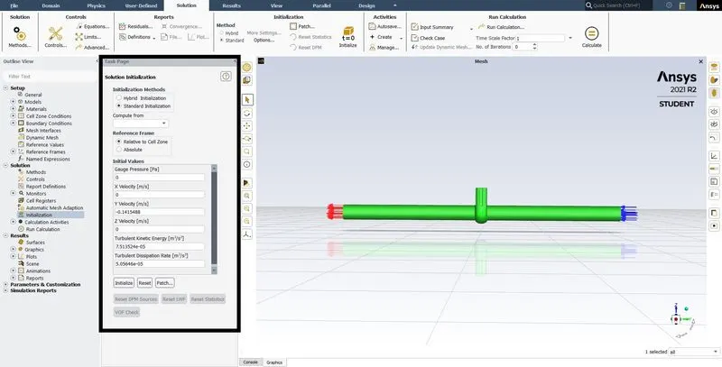
*Initialization of the solution is done for standard and the value is computed from the input parameters.
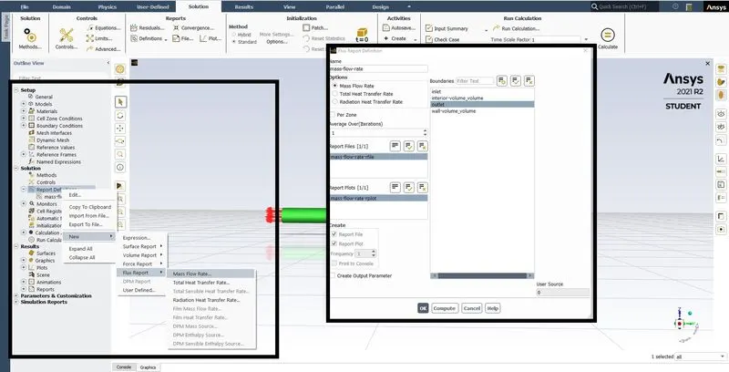
*Report definition is done by creating a report for Mass flow rate and total pressure at the outlet.
*Parametric study is done for the lift for the valve of 10% to 80%.
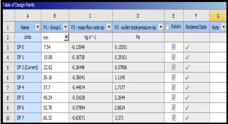
CASE 10% lift (7.54 mm)
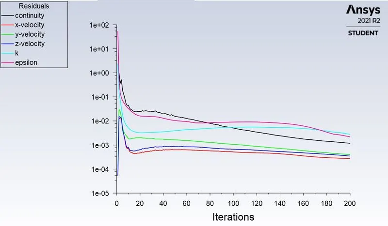
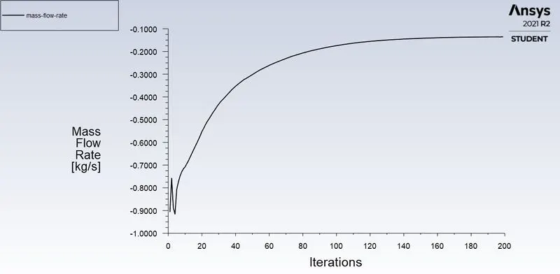
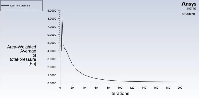
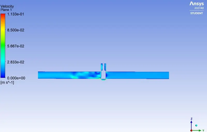
At lift of 10% (7.54 mm)
mass flow rate= 0.13547 `(kg)/sec`
Flow rate Q = `3.6*0.13547 ((m^3)/(hr))`
`Q= 0.487692 ((m^3)/(hr))`
`K_v=Q*sqrt((SG)/(Delta P)) ((m^3)/(hr))`
SG=1,
`Delta P=(P_i-P_o)` in Bars.
`K_v=0.487692*sqrt((1)/(9.8170e^-5)) ((m^3)/(hr))`
`K_v=49.2123((m^3)/(hr))`
`C_v=(K_v)/(0.865)`
`C_v=49.2123/0.865`
`C_v=56.8921`
CASE 20% lift (15.08 mm)
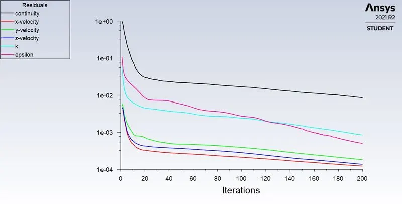
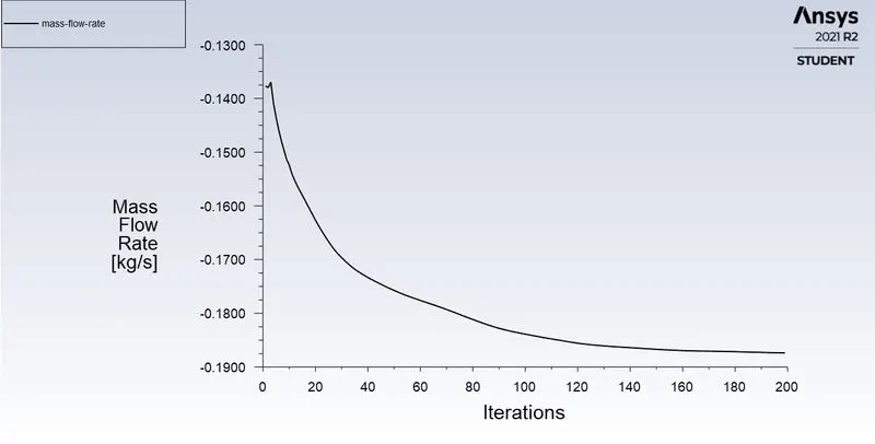
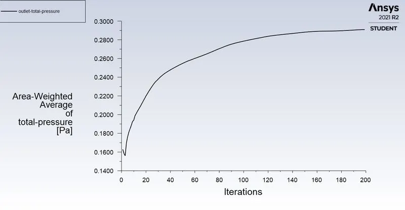
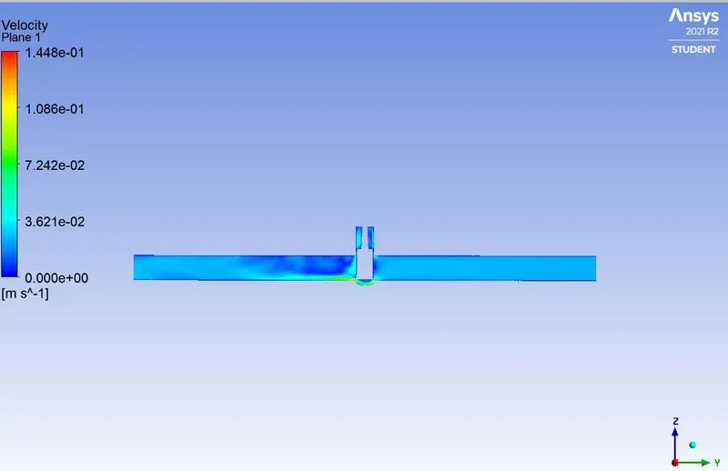
At lift of 20% (15.08 mm)
mass flow rate= 0.18738 `(kg)/sec`
Flow rate Q = `3.6*0.18738 ((m^3)/(hr))`
`Q= 0.6745 ((m^3)/(hr))`
`K_v=Q*sqrt((SG)/(Delta P)) ((m^3)/(hr))`
SG=1,
`Delta P=(P_i-P_o)` in Bars.
`K_v=0.674568*sqrt((1)/(9.70e^-5)) ((m^3)/(hr))`
`K_v=68.4602((m^3)/(hr))`
`C_v=(K_v)/(0.865)`
`C_v=68.460/0.865`
`C_v=79.1735`
CASE 30% lift (22.62 mm)
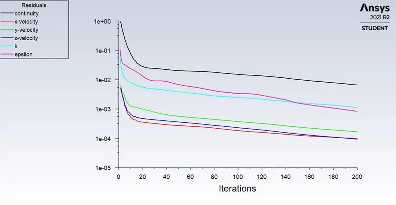
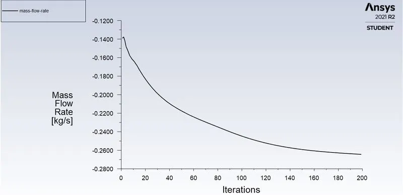
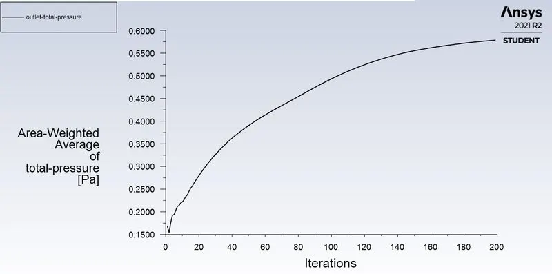
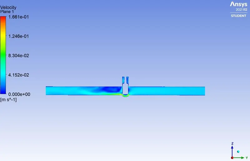
At lift of 30% (22.62 mm)
mass flow rate= 0.26448`(kg)/sec`
Flow rate Q = `3.6*0.26448((m^3)/(hr))`
`Q= 0.9521 ((m^3)/(hr))`
`K_v=Q*sqrt((SG)/(Delta P)) ((m^3)/(hr))`
SG=1,
`Delta P=(P_i-P_o)` in Bars.
`K_v=0.952128*sqrt((1)/(9.424 e^-5)) ((m^3)/(hr))`
`K_v=98.07649((m^3)/(hr))`
`C_v=(K_v)/(0.865)`
`C_v=98.07649/0.865`
`C_v=113.3832`
CASE 40% lift (30.16 mm)
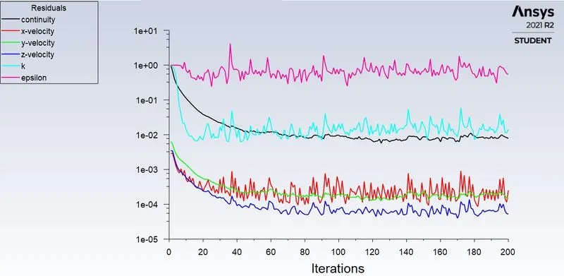
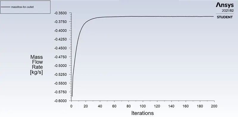
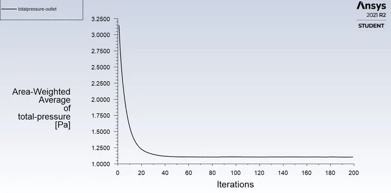
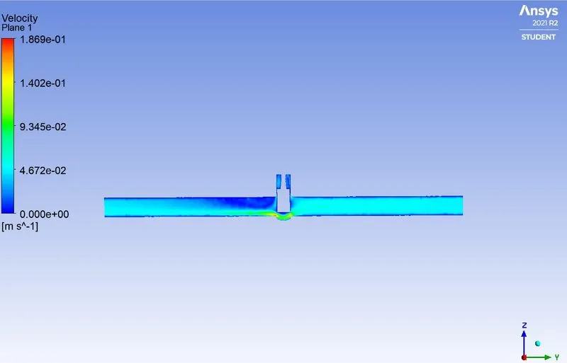
At lift of 40% (30.16 mm)
mass flow rate= 0.36041 `(kg)/sec`
Flow rate Q = `3.6*0.36041 ((m^3)/(hr))`
`Q= 1.297 ((m^3)/(hr))`
`K_v=Q*sqrt((SG)/(Delta P)) ((m^3)/(hr))`
SG=1,
`Delta P=(P_i-P_o)` in Bars.
`K_v=1.297 *sqrt((1)/(8.885e^-5)) ((m^3)/(hr))`
`K_v=137.593((m^3)/(hr))`
`C_v=(K_v)/(0.865)`
`C_v=137.5938/0.865`
`C_v=159.068`
CASE 50% lift (37.7 mm)
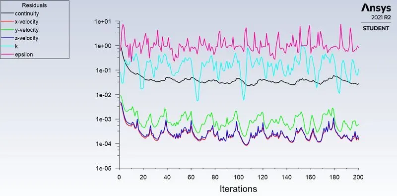
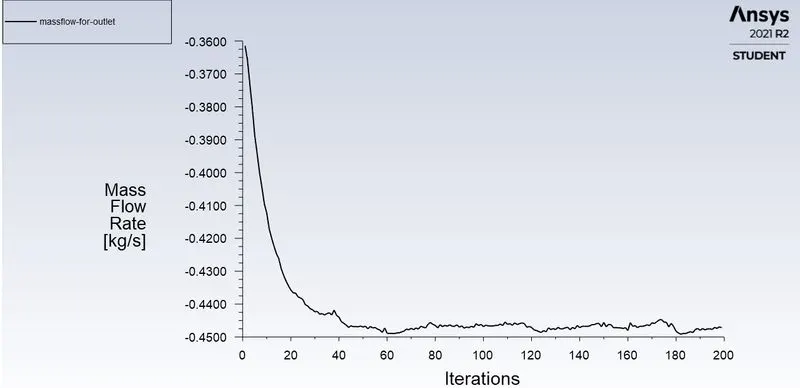
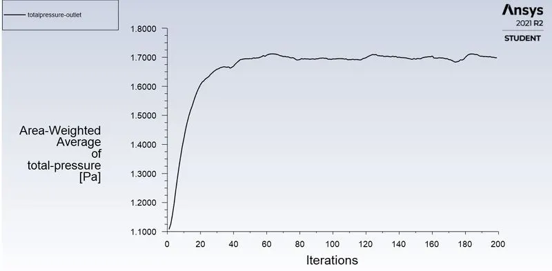
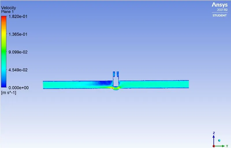
At lift of 50% (37.7 mm)
mass flow rate= 0.44974 `(kg)/sec`
Flow rate Q = `3.6*0.44974((m^3)/(hr))`
`Q= 1.6190((m^3)/(hr))`
`K_v=Q*sqrt((SG)/(Delta P)) ((m^3)/(hr))`
SG=1,
`Delta P=(P_i-P_o)` in Bars.
`K_v=1.6190*sqrt((1)/(8.23e^-5)) ((m^3)/(hr))`
`K_v=177.89((m^3)/(hr))`
`C_v=(K_v)/(0.865)`
`C_v=177.89/0.865`
`C_v=205.6625`
CASE 60% lift (45.24 mm)
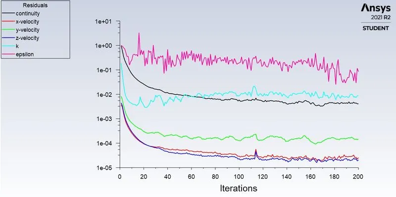
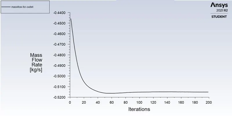
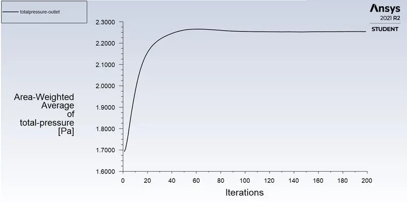
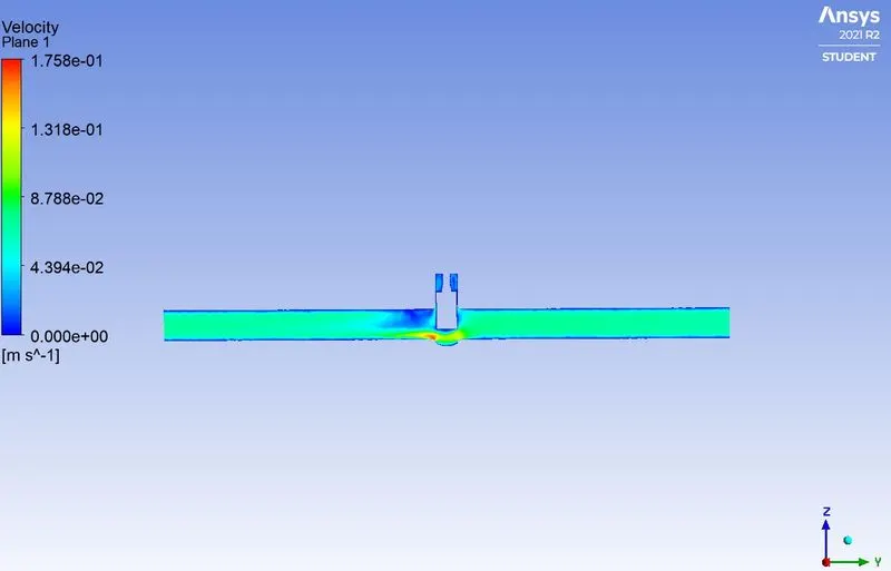
At lift of 60% (45.24 mm)
mass flow rate=0.5162 `(kg)/sec`
Flow rate Q = `3.6*0.13547 ((m^3)/(hr))`
`Q= 0.487692 ((m^3)/(hr))`
`K_v=Q*sqrt((SG)/(Delta P)) ((m^3)/(hr))`
SG=1,
`Delta P=(P_i-P_o)` in Bars.
`K_v=0.487692*sqrt((1)/(9.8170e^-5)) ((m^3)/(hr))`
`K_v=206.949((m^3)/(hr))`
`C_v=(K_v)/(0.865)`
`C_v=211.3191/0.865`
`C_v=244.299`
CASE 70% lift (52.78 mm)
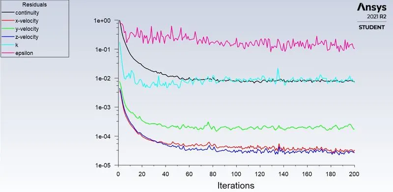
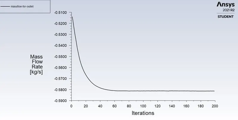
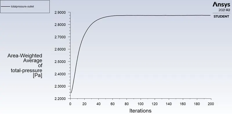
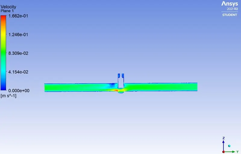
At lift of 70% (52.78 mm)
mass flow rate= 0.57994 `(kg)/sec`
Flow rate Q = `3.6*0.57994 ((m^3)/(hr))`
`Q= 2.0877 ((m^3)/(hr))`
`K_v=Q*sqrt((SG)/(Delta P)) ((m^3)/(hr))`
SG=1,
`Delta P=(P_i-P_o)` in Bars.
`K_v=2.0877*sqrt((1)/(7.0376e^-5)) ((m^3)/(hr))`
`K_v=247.1109((m^3)/(hr))`
`C_v=(K_v)/(0.865)`
`C_v=247.1109/0.865`
`C_v=285.677`
CASE 80% lift (60.32 mm)
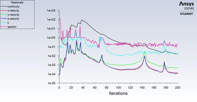
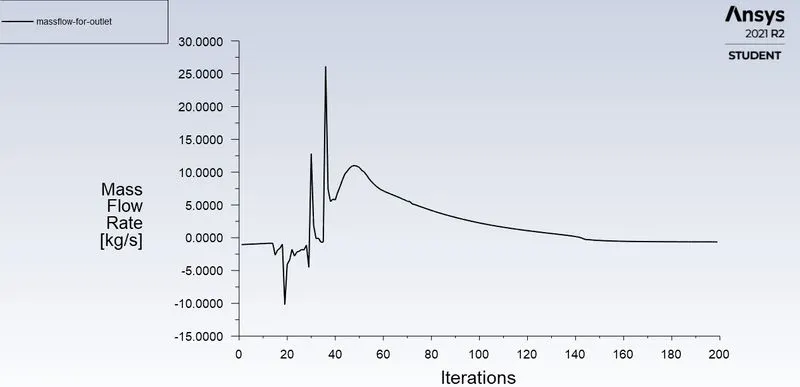
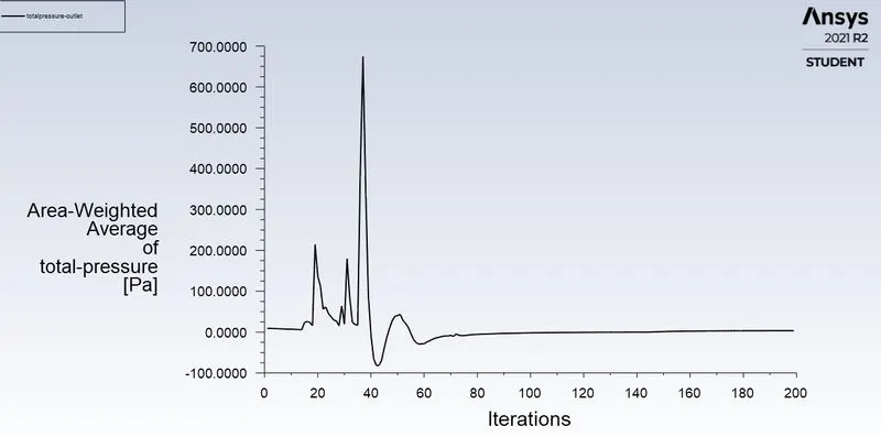
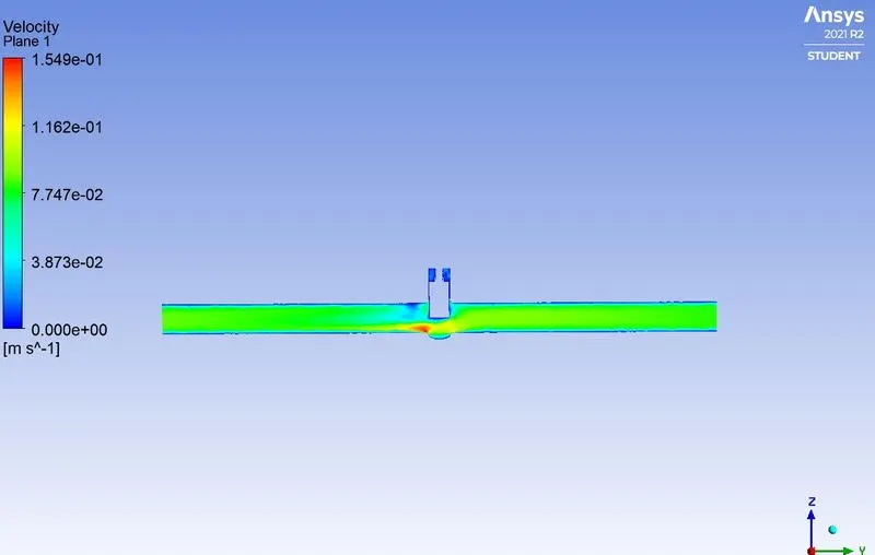
At lift of 80% (60.32 mm)
mass flow rate= 0.63071 `(kg)/sec`
Flow rate Q = `3.6*0.63071 ((m^3)/(hr))`
`Q= 2.2705((m^3)/(hr))`
`K_v=Q*sqrt((SG)/(Delta P)) ((m^3)/(hr))`
SG=1,
`Delta P=(P_i-P_o)` in Bars.
`K_v=2.2705*sqrt((1)/(6.629e^-5)) ((m^3)/(hr))`
`K_v=278.8052((m^3)/(hr))`
`C_v=(K_v)/(0.865)`
`C_v=278.8052/0.865`
`C_v=322.3188`
TABULATED RESULT
|
Lift of Gate Disc (%) |
Lift of Gate Disc (mm) |
Mass Flow Rate`(Kg)/(s)` |
Inlet Pressure (Pa) |
Outlet Pressure (Pa) |
Pressure Difference `e^-5`Bar |
Flow Factor `(m^3)/(h)` |
Flow Coefficient |
Max Velocity `(m/s)` |
|
10% |
7.54 (mm) |
0.13549 |
10 |
0.15351 |
9.84649 |
49.2123 |
56.8921 |
0.1133 |
|
20% |
15.08 (mm) |
0.18738 |
10 |
0.29101 |
9.70899 |
68.4602 |
79.1735 |
0.1448 |
|
30% |
22.62 (mm) |
0.26448 |
10 |
0.57906 |
9.42094 |
98.6764 |
113.3832 |
0.1661 |
|
40% |
30.16 (mm) |
0.36041 |
10 |
1.1145 |
8.8855 |
137.593 |
159.068 |
0.1869 |
|
50% |
37.7 (mm) |
0.44974 |
10 |
1.7177 |
8.2823 |
177.89 |
205.6625 |
0.1820 |
|
60% |
45.24 (mm) |
0.51628 |
10 |
2.2644 |
7.7357 |
206.949 |
244.299 |
0.1758 |
|
70% |
52.78 (mm) |
0.57994 |
10 |
2.8624 |
7.1376 |
247.1109 |
285.677 |
0.1662 |
|
80% |
60.32 (mm) |
0.63071 |
10 |
3.371 |
6.629 |
278.8052 |
322.3188 |
0.1549 |
GRAPH
CONCLUSION:
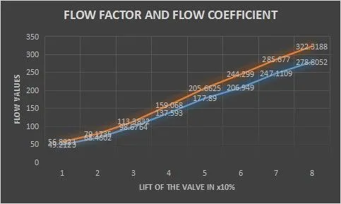
- The Flow Coefficient and Flow Factor increase as the Mass Flow Rate through the valve increases.
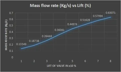
- Mass Flow Rate increases as the lift of the gate disc increases.
- The low lift height refers to the higher pressure drop and thus low flow rate through the valve.
- Pressure difference decreases with an increase in the lift of the gate disc.