Week 9 Machining with Planer Challenge
EXPLICIT DYNAMIC ANALYSIS OF MACHINING WITH PLANER USING ANSYS WORKBENCH
OBJECTIVE
- To perform explicit dynamic analysis of machining with planer for the following two different cases of cutting velocity,
- Case-1: Cutting velocity=20000 mm/s
- Case-2: Cutting velocity=15000 mm/s
- To find out Directional Deformation, Equivalent (v-m) Stress, Equivalent Plastic Strain and Temperature of the body for both the cases and compare the results.
1. THEORY
1.1 Planer Machining.
Planer Machine is a machine in which unwanted material is cut from the workpiece to produce a flat surface on the workpiece. Unlike Shaper Machine, in this machine, more than one tool can be set and perform an operation.
The principle of the planer machine is the concept of relative tool-work motions. Reciprocation of the tool or job and the slow, intermittent transverse feed motions are imparted to the job or tool by the fast-straight path cutting motion.
Al the operations done in planning machines can be done in the shaping machine. Stroke length, larger size, and higher rigidity enable the planning machines to do more heavy-duty work on large jobs and their long surfaces.
It produces planes and flat surfaces with a single-point cutting tool. A planer machine is large and massive as compared to a shaper machine. The planer can do machining heavy workpiece, which cannot be done on a shaper surface.
In this project, the unwanted materials are removed from the work piece by shearing the work piece using cutting tool with two different cutting velocities.
2. ANALYSIS SETUP
2.1 Geometry:
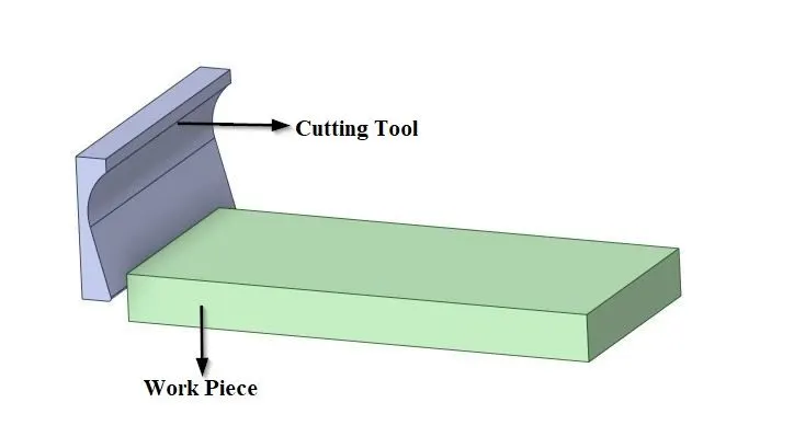
Fig.2.1 3D model of machining with planer.
The given 3D model of machining with planer is imported into SpaceClaim. It consists of work piece and cutting tool.
2.2 Material Properties:
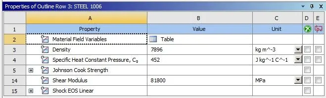
Fig.2.2 Material property details of wok piece.
The material assigned for work piece is steel 1006 and for cutting tool is structural steel. The stiffness behavior of cutting tool is set as ‘Rigid’ whereas, for work piece it is set as ‘Flexible’.
2.3 Meshing:
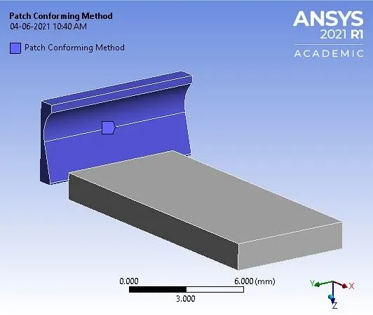
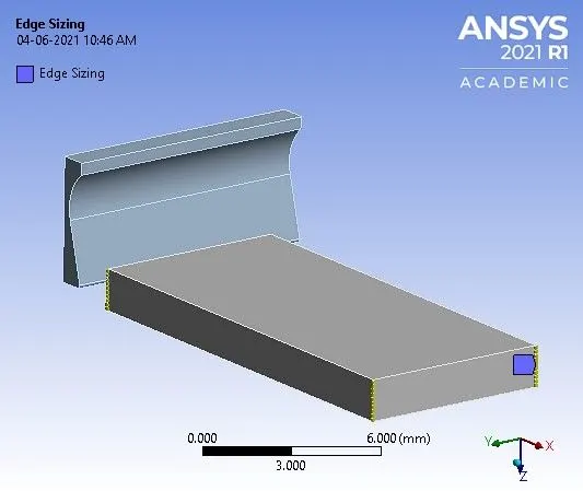
a. Patch conforming method specified for cutting tool. b. Edge sizing specified for work piece.
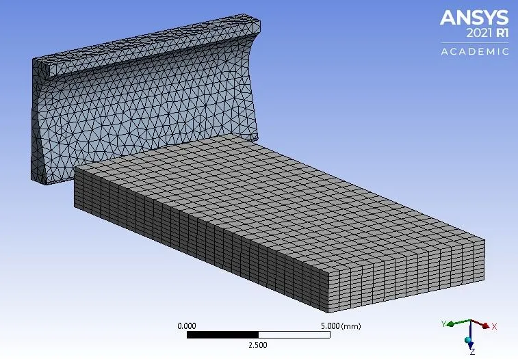
Fig.2.3 Meshing details of machining with planer model.
The cutting tool model is selected using body filter and specified with patch conforming method for meshing with tetrahedral elements. The shorter edges of work piece are selected using edge filter and divided into 10 divisions for meshing. The total number of nodes and elements generated are 6557 and 10081 respectively.
Note: The academic version of software has the problem size limit of 128k nodes or elements.
2.4 Boundary Conditions:
2.4.1 Analysis settings:
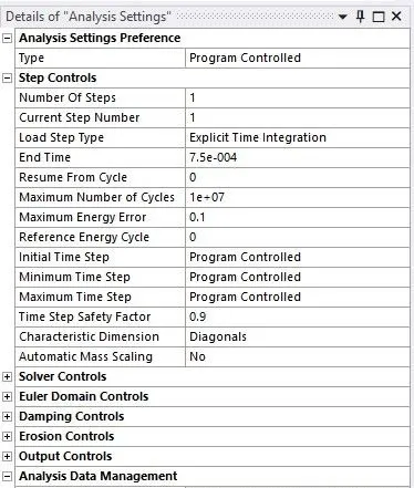
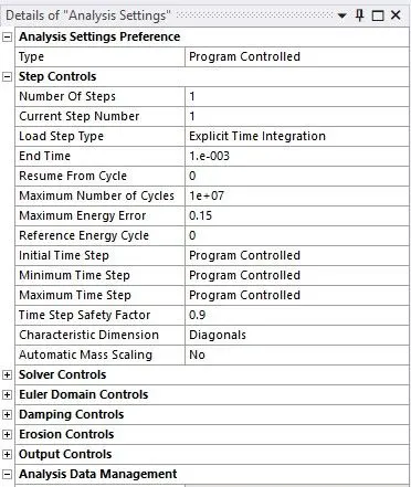
a. Analysis setting for case-1. b. Analysis setting for case-2.
Fig.2.4.1 Analysis settings.
In the analysis settings the number of steps considered is 1. The end time for case-1 is 7.5e-004 and for case-2, it is 1e-003. The maximum no. of cycles is 1e+07 for both the cases. The maximum energy error for case-1 is 0.1 and for case-2, it is 0.15. The initial, minimum and maximum time step is set to ‘Program Controlled’.
2.4.2 Boundary condition:
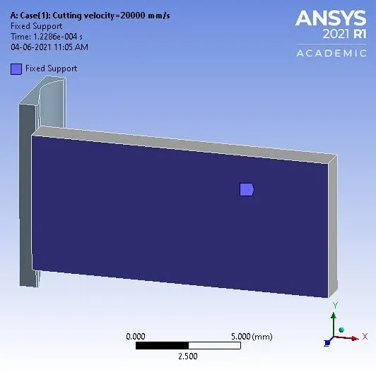
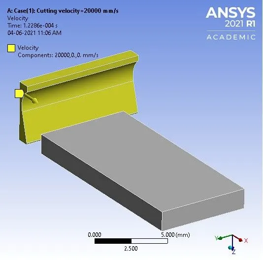
a. Fixed support specified at the bottom surface of work piece. b. Cutting velocity specified to cutting tool along x-axis.
Fig.2.5.2 Boundary conditions applied to machining with planer model.
The bottom surface of workpiece is fixed. For case-1, the cutting velocity specified along x-axis is 20000 mm/s and for case-2, the cutting velocity specified is 15000 mm/s.
3. RESULTS AND DISCUSSIONS
3.1 Case-1: Cutting velocity=20000 mm/s.
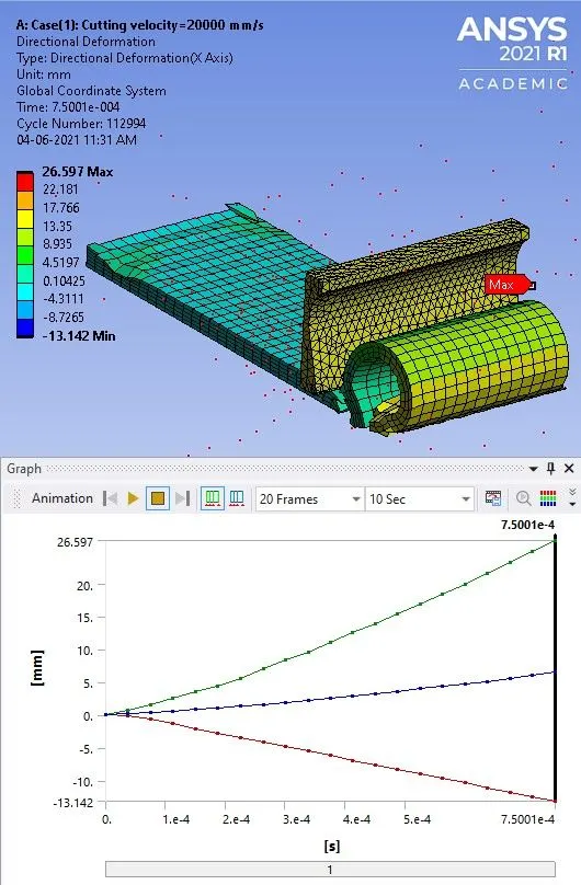
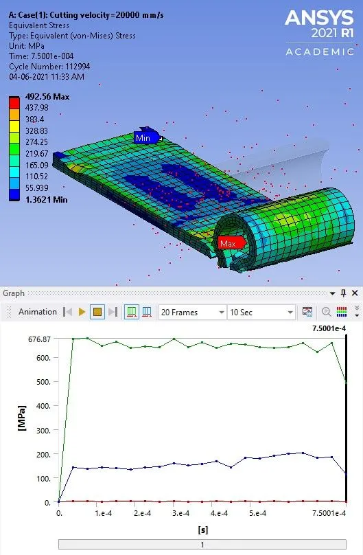
a. Directional Deformation. b. Equivalent (v-m) Stress.
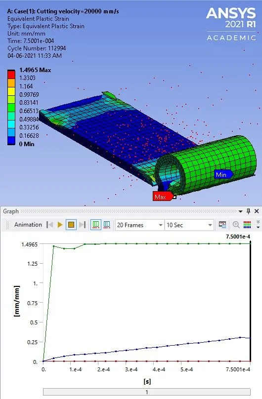
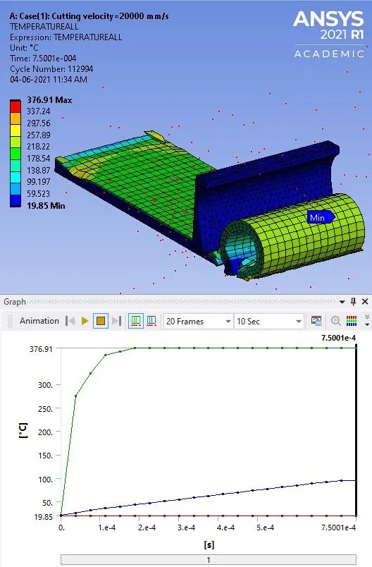
c. Equivalent Plastic Strain. d. Temperature.
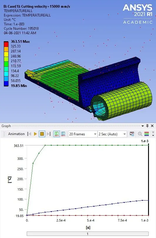
3.2 Case-2: Cutting velocity=15000 mm/s.
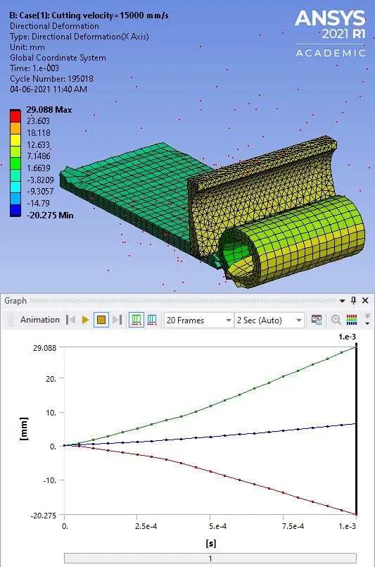
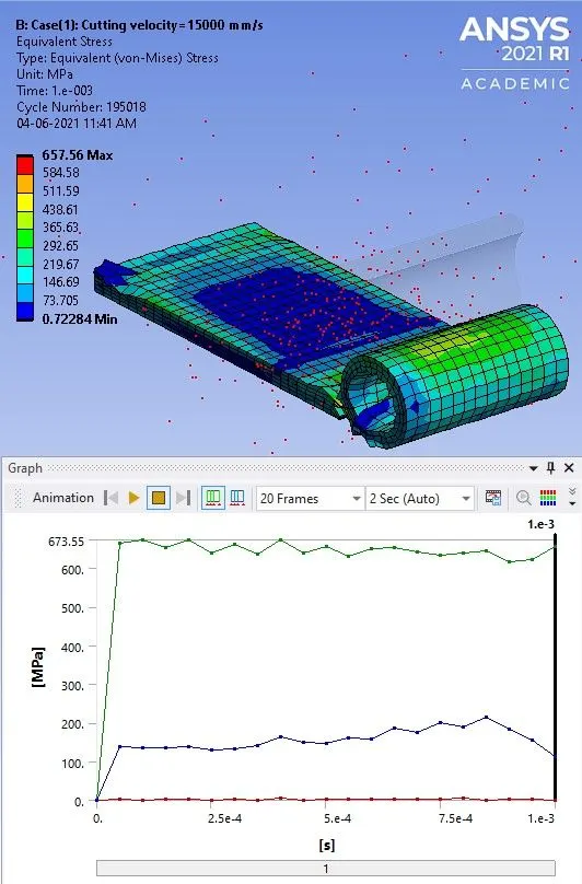
a. Directional Deformation. b. Equivalent (v-m) Stress.
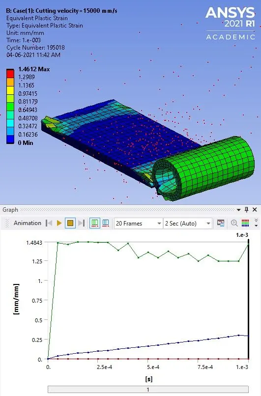
c. Equivalent Plastic Strain. d. Temperature.
3.3 Comparison of Results:

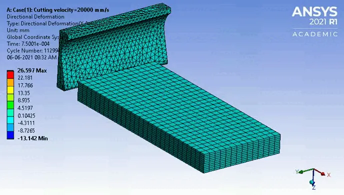
From the table, it is observed that, the value of maximum directional deformation along x-axis for case-1 is 26.597 mm, whereas for case-2, it is 29.080 mm.
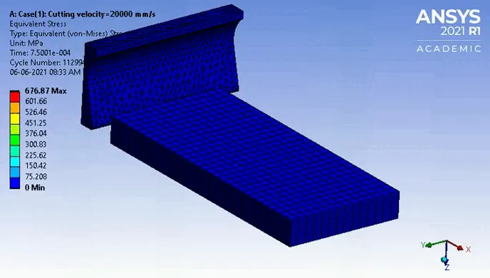
The maximum v-m stress was developed in the chips as well as at the interface of workpiece and cutting tool during cutting operation. The maximum value of v-m stress for case-1 is 676.87 MPa, which is more compared case-2, since the magnitude of cutting velocity is more in case-1.
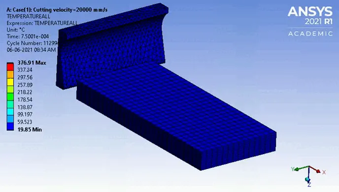
It is observed that, the temperature is maximum at the interface of workpiece and cutting tool. The maximum temperature developed in the case-1 is 376.91 oC which is more compared to case-2, because cutting velocity for case-1 is more compared to case-2.
4. ANIMATION OF RESULTS:
3.1 Case-1: Cutting velocity=20000 mm/s.
a. Directional Deformation.
b. Equivalent (v-m) Stress.
c. Temperature.
3.2 Case-2: Cutting velocity=15000 mm/s.
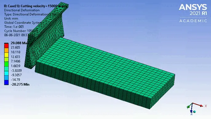
a. Directional Deformation.
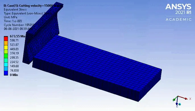
b. Equivalent (v-m) Stress.
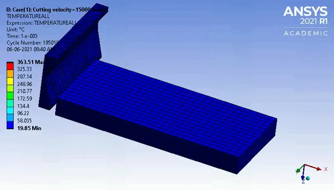
c. Temperature.
CONCLUSION
- Explicit dynamic analysis of machining with planer was carried out successfully for the following two different cases of cutting velocity,
- Case-1: Cutting velocity=20000 mm/s
- Case-2: Cutting velocity=15000 mm/s
- The directional deformation along x-axis for case-1 is more compared to case-2,
- The maximum equivalent (v-m) stress was developed in the chips as well as at the interface of workpiece and cutting tool during cutting operation. The maximum equivalent (v-m) stress for case-1 is more compared to case-2.
- The temperature is maximum at the interface of workpiece and cutting tool. The maximum temperature developed in the case-1 was more compared to case-2, because cutting velocity for case-1 is more compared to case-2.