Week 9-Creation of 1D Connectors Challenge
Assignment:8
Objective: To create 1D Connectors to form connections in the given model.
WORKFLOW:

Connectors: What are they & why use them?
Geometric entities that define connections between other entities
- Used for welding, bolts, adhesives, etc.
- Link geometry or FE entities
- Can be “realized” into FE representations of welds, etc. for any supported solver
- Connectors allow for easy and rapid creation of FE welds, bolts, adhesives, etc. Interactively or from:
- XML file
- MCF (master connectors file)
- Spot welds only
- Switching between different FE configurations of welds, bolts, adhesives, etc.
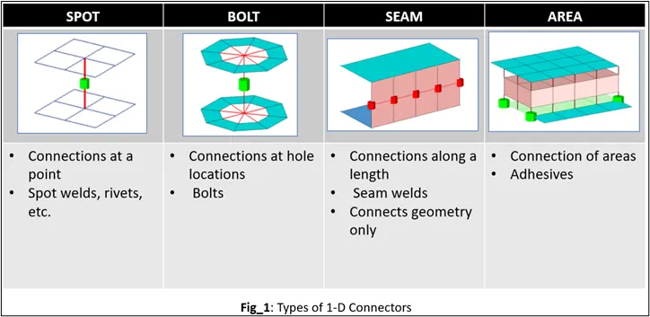
Types of Connectors:
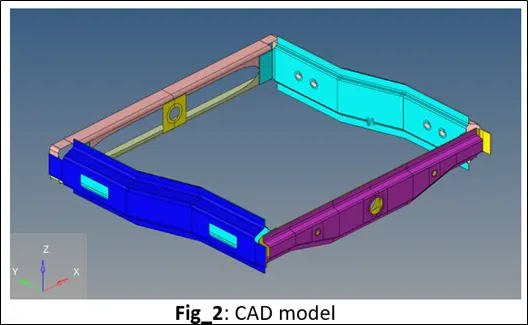
CAD
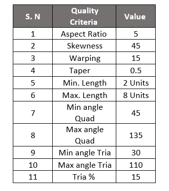
Mesh Quality Parameters:
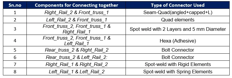
Connectors to be formed :
Procedure:
- Isolate the two components and locate the area where the two or more componenets need to be joined using a connector.
- Click on 1-D Panel
- Go to “connector” sub-panel
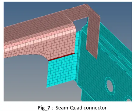
- Choose the Seam connector
- Click on create, use nodelist for the “location” and select by path from the drop down menu
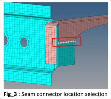
- Choose the appropriate spacing depending on the mesh size
- Select the two components to be joined for the “connect what”
- Depending on the gap between the two bodies provide the tolerance value
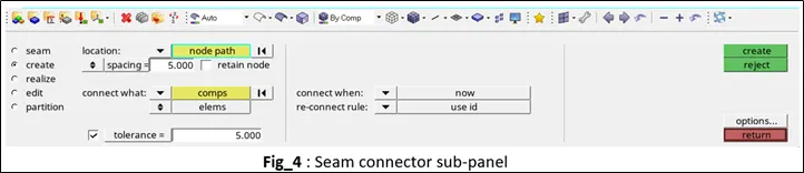
- Click on “Create”
- Click on “realize”, select the connector just created, choose the type as Seam-Quad(angled+capped+L)
- Click on realize
- On the connector browser we can visualize the connectors and their realization as well as their properties, errors, etc.
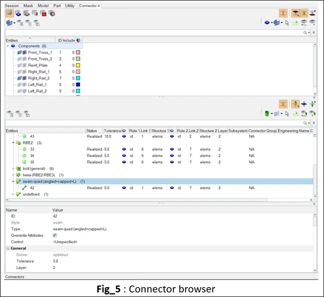
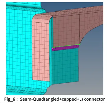
Similarly other connector types can be chosen from the connector option and based on the type of connector required we can create connections between these components.
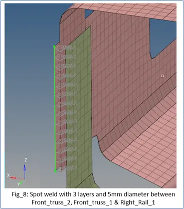
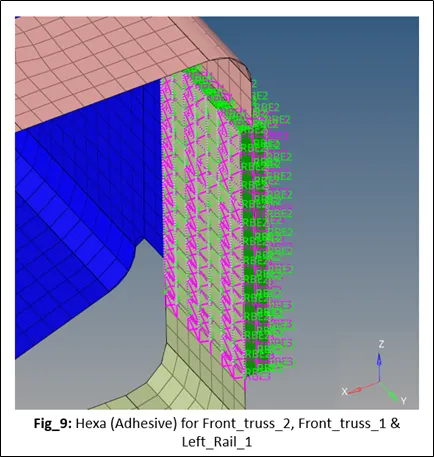
As for Area connector (Adhesives) we cannot change the number of layers we created two separate connections between the three bodies.
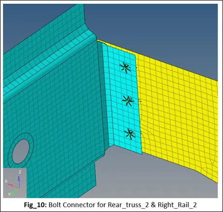
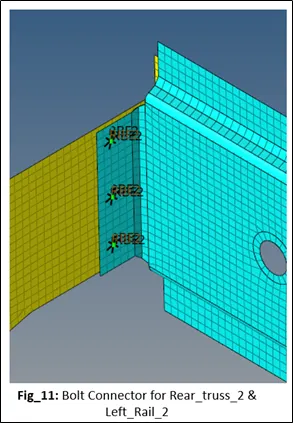
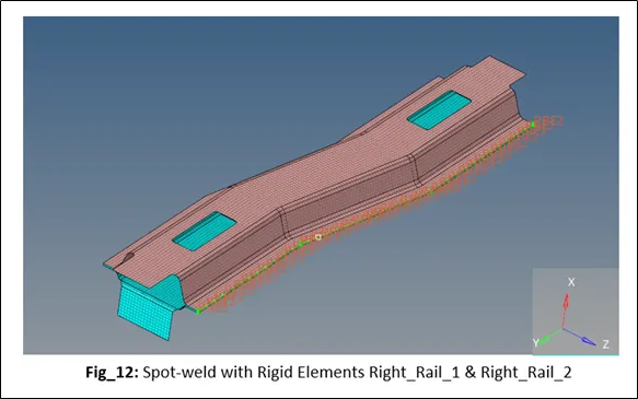
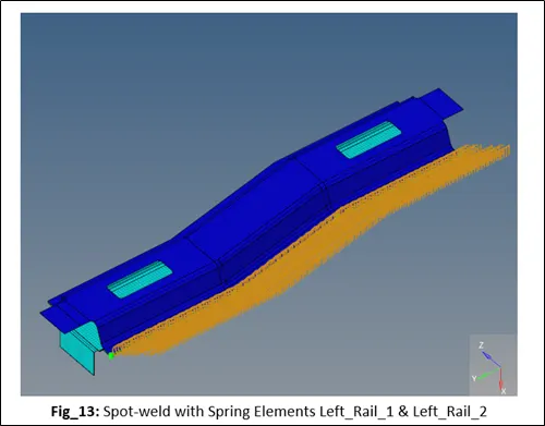
RESULT: Required connectors are created & realized succesfully