DC Motor Control
OBJECTIVES OF THE PROJECT:
- Run MATLAB demo ‘Speed control of a DC motor using BJT H-bridge’. Modify the model such that armature current doesn’t shoot up when motor changes direction from forward to reverse.
- Refer to help section of ‘The Four-Quadrant Chopper DC Drive (DC7) block’. Compare it with H-bridge model.
- Make a suitable EV model using DC7 block and make result report.
INTRODUCTION:
Battery voltage is actually quite well regulated, but frequently we will want to change the voltage to a lower or higher value, usually to control the speed of a motor. If we want to produce a variable voltage (e.g. for a motor) from the more-or-less fixed voltage of a battery. Whatever change is required, it is done using ‘switching’ or ‘chopping’ circuits.
IGBT
- The insulated gate bipolar transistor (IGBT) is essentially an integrated circuit combining a conventional bipolar transistor and a MOSFET.
- They require a fairly low voltage, with negligible current at the gate to turn on.
The main current flow is from the collector to the emitter, and this path has the characteristics of a p-n junction.
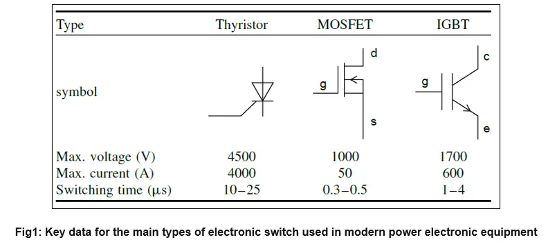
1.Speed control of a DC motor using BJT H-bridge
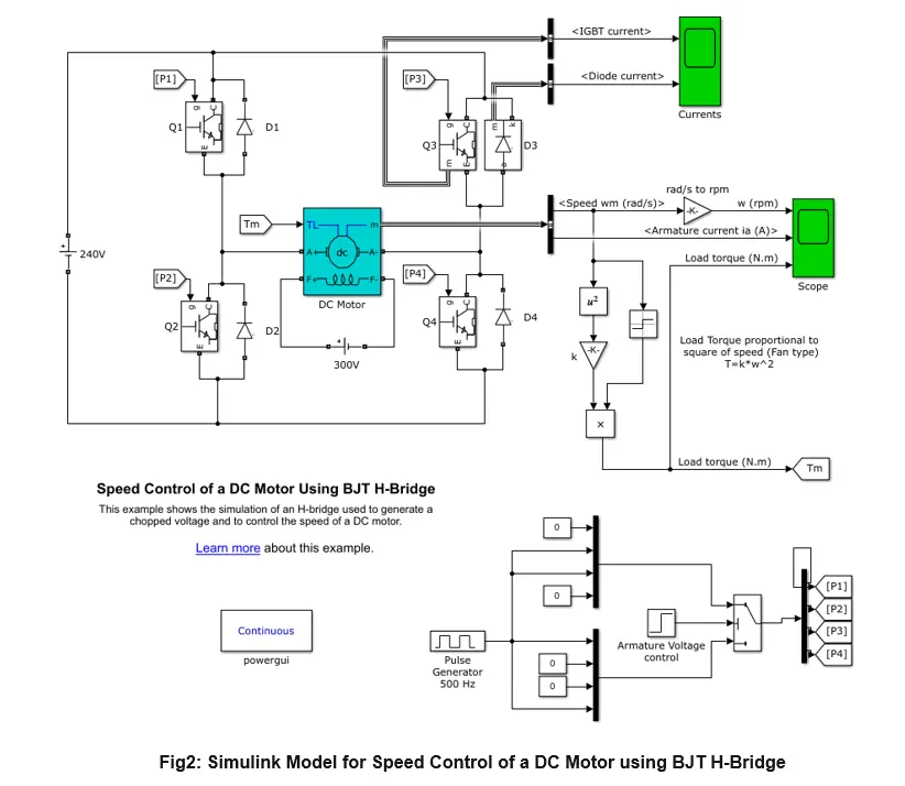
- This example shows the simulation of an H-bridge used to generate a chopped voltage and to control the speed of a DC motor.
- The IGBT block does not simulate the gate current controlling the BJT or IGBT. The switch is controlled by a Simulink® signal (1/0). The DC motor uses the present model (5 HP 24V 1750 rpm). It simulates a fan type load (where Load torque is proportional to square of speed).
- The armature mean voltage can be varied from 0 to 240 V when the duty cycle (specified in the Pulse Generator block) is varied from 0 to 100%.
- The H-bridge consists of four BJT/Diode pairs (BJT simulated by IGBT models). Two transistors are switched simultaneously: Q1 and Q4 or Q2 and Q3. When Q1 and Q4 are fired, a positive voltage is applied to the motor and diodes D2-D3 operate as free-wheeling diodes when Q1 and Q4 are switched off. When Q2 and Q3 are fired, a negative voltage is applied to the motor and diodes D1-D4 operate as free-wheeling diodes when Q2 and Q3 are switched off.
Simulation
- The motor starts in the positive direction with a duty cycle of 75% (mean DC voltage of 180V). At t= 0.5 sec., the armature voltage is suddenly reversed and the motor runs in the negative direction.
- 'Scope' shows motor speed, armature current and load torque and 'Currents' shows currents flowing in BJT Q3 and diode D3.
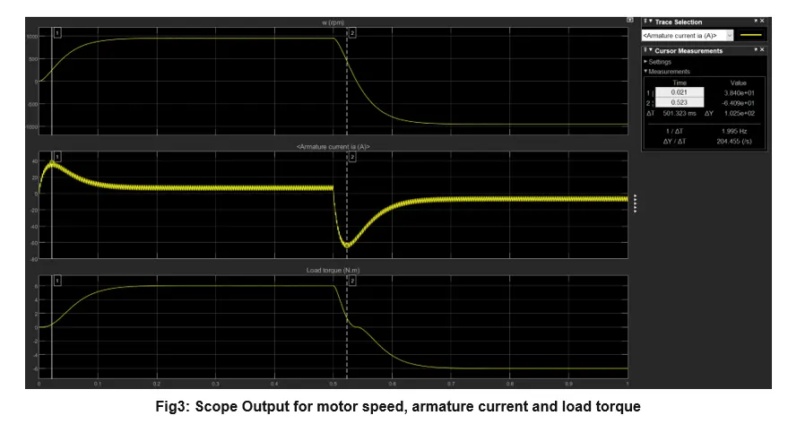
- We can observe the change of motor speed based on the voltage change in the circuit.
- For the first 0.5 sec we can see the Clockwise operation & after that when the switches Q2 & Q3 are operated, we observe the counter clockwise direction of motor operation.
- In this transition of positive to negative direction of rotation we observe a high surge in current, this is due to the transient switching occurring in the circuit.
- As there is already current flowing in the circuit & on changing of switches after 0.5 sec, the current in the circuit adds to the changed direction of current and we observe a surge.
- This happens very quickly (0.023sec) & we can rectify this surge by changing the duty cycle, a optimal duty cycle will ensure proper distribution between the ON/OFF states of the switching and will reduce this surge.
- But this will come at the cost of a lower torque and speed of the motor.
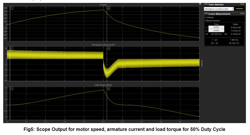
50% Duty Cycle:
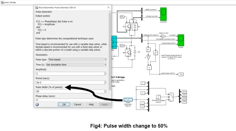
For 50% Duty Cycle the Switches will remain ON for 50% time(0.001secs) and OFF for 0.001 secs.
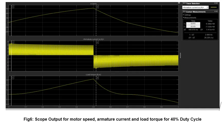
40% Duty Cycle:
For 40% Duty Cycle the Switches will remain ON for 40% time(0.0008secs) and OFF for 0.0012 secs.
OBSERVATION:
- We can observe that for 50% duty cycle there is still a significant surge seen in the output for current, so we need to move to a lower duty cycle.
- With 40% duty cycle we observe that the surge is no longer visible, hence with this duty cycle the current will be in more sync with the switching.
- We can also observe a significant drop in the motor speed, and torque as well.
2.The Four-Quadrant Chopper DC Drive (DC7) block
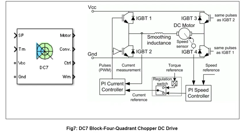
- The Four-Quadrant Chopper DC Drive (DC7)block represents a four-quadrant, DC-supplied, chopper (or DC-DC PWM converter) drive for DC motors.
- The speed control loop outputs the reference armature current of the machine. Using a PI current controller, the chopper duty cycle corresponding to the commanded armature current is derived
- The main advantage of this drive, compared with other DC drives, is that it can operate in all four quadrants (forward motoring, reverse regeneration, reverse motoring, and forward regeneration).
- In addition, due to the use of high switching frequency DC-DC converters, a lower armature current ripple (compared with thyristor-based DC drives) is obtained.
|
BJT-H Bridge Model |
DC-7 Drive |
|
1.Operates in 1st and 3rd Quadrant (Forward Motoring & Reverse Motoring) |
1.Operates in all 4 Quadrants. (Forward Motoring & Breaking, Reverse Motoring & Braking) |
|
2.Closed loop chopper, i.e takes feedback from the output to change the input. |
2.Open loop chopper. |
|
3.Armature current oscillations are reduced by a smoothing inductance connected in series with the armature circuit. |
3.Need lower duty cycles for reducing armature current ripples. |
|
4.PI Controllers are used for dynamic control of pulse width. |
4.We provide a fixed value of Pulse width for the simulation, as there is no feedback in the circuit. |
|
5.Continuous computation, requires extensive computation. |
5.Discrete Computation for the model, hence quick. |
3.EV model using DC7 block
- The first regulator is a speed regulator, followed by a current regulator. The speed regulator outputs the armature current reference (in p.u.) used by the current controller in order to obtain the electromagnetic torque needed to reach the desired speed.
- The speed reference change rate follows acceleration and deceleration ramps in order to avoid sudden reference changes that could cause armature over-current and destabilize the system.
- The current regulator controls the armature current by computing the appropriate duty ratios of the 5 kHz pulses of the four IGBT devices (Pulse Width Modulation).
- For proper system behavior, the instantaneous pulse values of IGBT devices 1 and 4 are opposite to those of IGBT devices 2 and 3. This generates the average armature voltage needed to obtain the desired armature current.
- In order to limit the amplitude of the current oscillations, a smoothing inductance is placed in series with the armature circuit.
Simulation
- We need a DC supply that would simulate the EV battery pack, for this we will use a DC energy source.
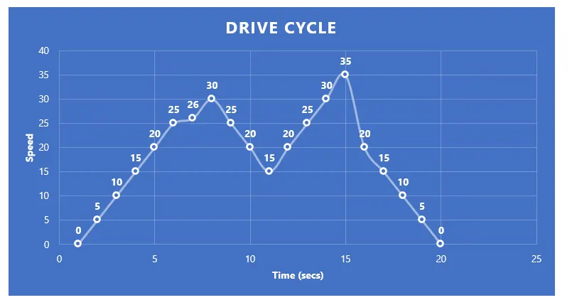
- For reference speed, we need to give the input of our drive cycle for the PI controller to evaluate the current and voltage inputs for the motor.
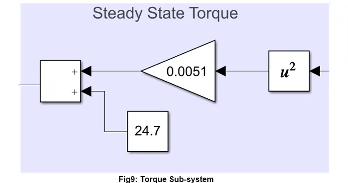
- For the mechanical Torque input, we will be using the Steady state operating conditions to obtain the torque which needs to be provided by the motor for the EV to operate.
- We will be using the equation `T_m=24.7+0.0051ω^2`
- This equation represents the steady state operating Torque.
- We will be making a subsystem of the blocks representing this equation.
- For the simulation time we need to provide appropriate time according to our driving cycle inputs.
SIMULINK MODEL
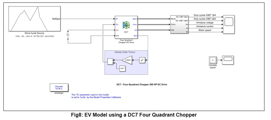
- DC Source= 100V
- Drive Cycle Used:
- Torque Block
Discussion:
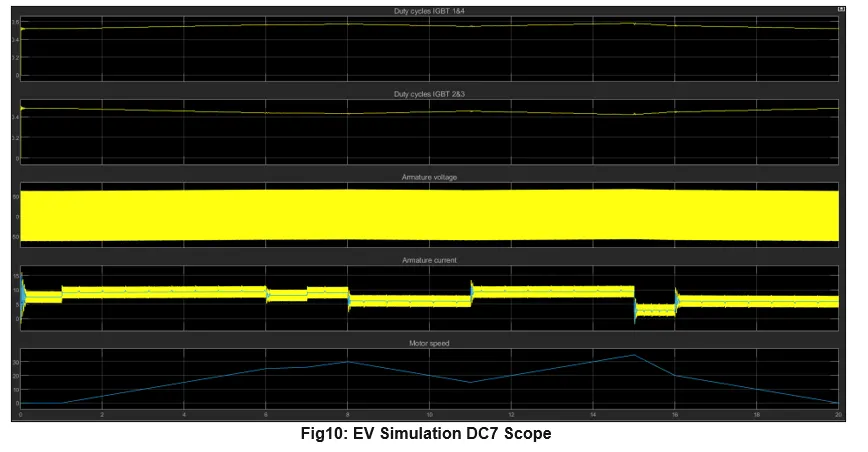
- We have 4 parameters being displayed in the output here; they are Current in the IGBT 1&4 and current in IGBT 2&3, along with that we have the Armature Voltage, Armature Current and Motor Speed.
- We can observe that the Motor operates in Sync with the drive cycle reference speed and is able to produce appropriate outputs.
- Coming to the duty cycles in the IGBT we can observe that the duty cycles vary according to the reference speed, in 1&4 we see a increase when there is a rise in speed while we see a decline in 2&3 during the same.
- We can observe the same kind of change in the current, with the sudden reduction in speed, we see a dip in current and a increase in IGBT 2&3 duty cycle.
CONCLUSION: Working understanding of power controllers in MATLAB Simulink is developed for BJT H Bridge and DC7 4 Quadrant DC Motor Chopper model.
References:
- https://skill-lync.com/projects/multi-quadrant-operation-of-dc-motor-in-simulink
- https://skill-lync.freshdesk.com/support/solutions/articles/43000571899-how-to-model-dc7-four-quadrant-chopper-200-hp-dc-drive
- https://www.mathworks.com/help/physmod/sps/ug/dc7-four-quadrant-chopper-200-hp-dc-drive.html