Week 4-1D Element Creation Challenge
Assignment:3
Objectives: Mesh the Given component with the Size of 5 Units. Create 1D elements on the following component with given cross-section and DOF
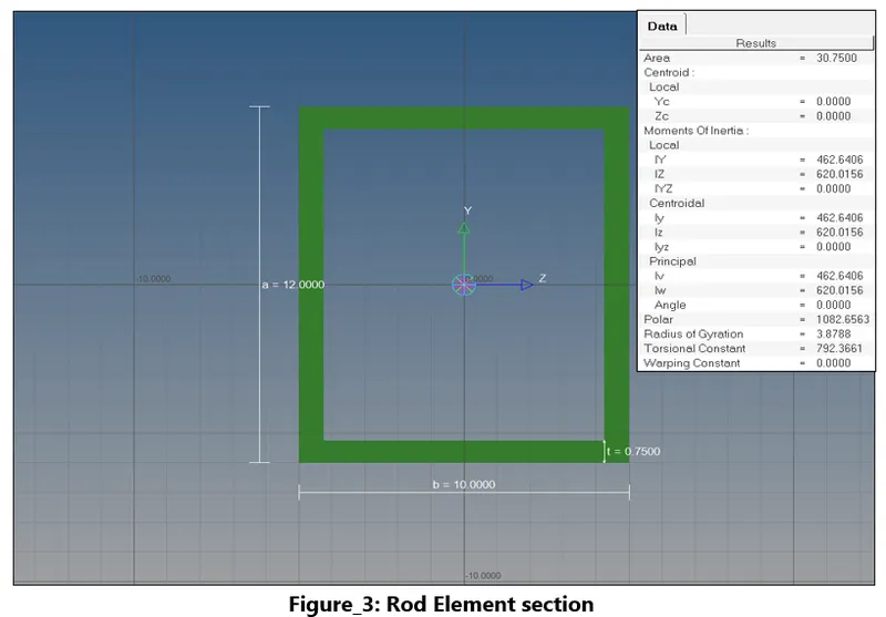
1.Rod element: - Translational DOF should be Constrained with RBE2 link
Cross-Section: BOX- Dimension a= 12 mm
dimension b=10 mm
Thickness t= 0.75 mm
2.Beam element: - All DOF should be constrained with RBE3 link
Cross-Section: I Section- Dimension a= 8 mm
Dimension b= 10 mm
Dimension c= 8.5 mm
Thickness t1= 0.75 mm
Thickness t2= .6 mm
Thickness t3= .6 mm
3.Bar element: - Constrain only xand y DOFs With RBE3 link
Cross-section: X section- Dimension DIM1= 5 mm
Thickness DIM2= 1.2 mm
Dimension DIM3= 10 mm
Thickness DIM4= 1.2mm
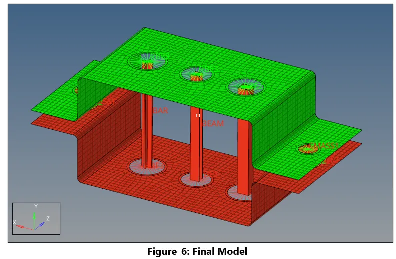
4. At d & e. Apply the massof magnitude 10 with the RBE2 link
5. Join the two components with Spring elements
Approach:
- Import the IGES CAD model into HM.
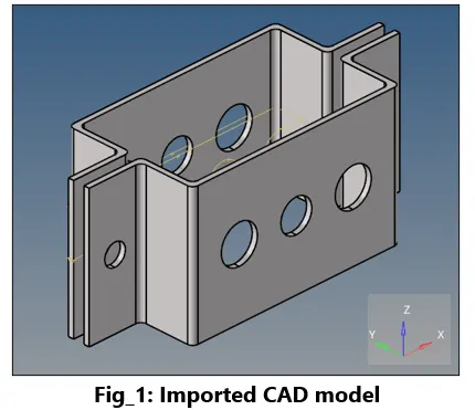
- Delete the unwanted line elements.
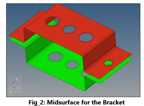
- Generate the Mid-Surface using auto-mi surface with Extraction option ‘’Offset’’ to capture the internal bends in the bracket along with proper surface splits.
- Create washer splits of standard 2.5 times the hole diameter using surface split subpanel.
- Create material property as per requirement
- Using 2-D panel, generate mesh using mixed elements with 5 units as element size using ‘’auto-mesh’’ subpanel.
- Tweak the number of nodes near the bends to have a better-quality mesh.
- Create properties card for the brackets and associate them with respective component.
- Create RBE-2 elements at location ‘’a’’ using 1-D elements panel
Procedure for Creating 1-D Elements
- Using 1-D elements panel, click on Hyberbeam option
- Create different types of beam sections as per the specification
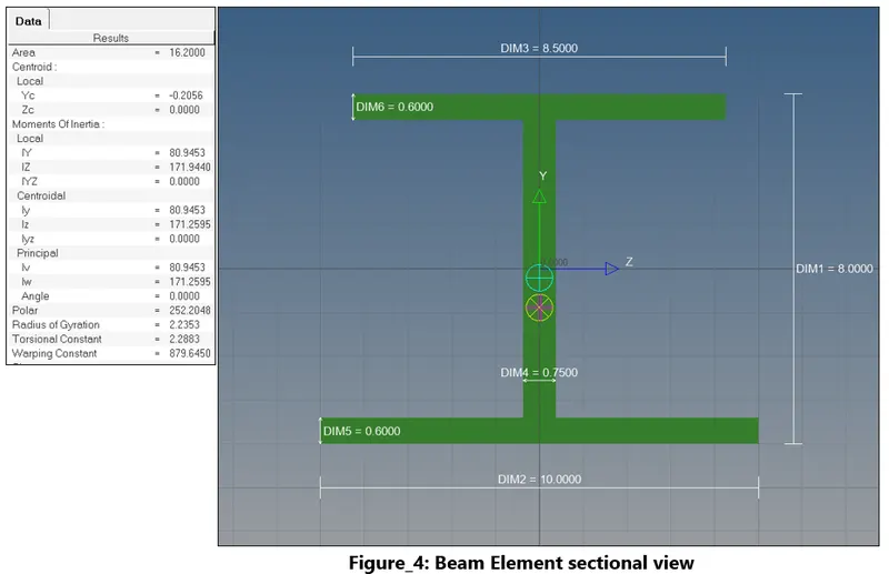
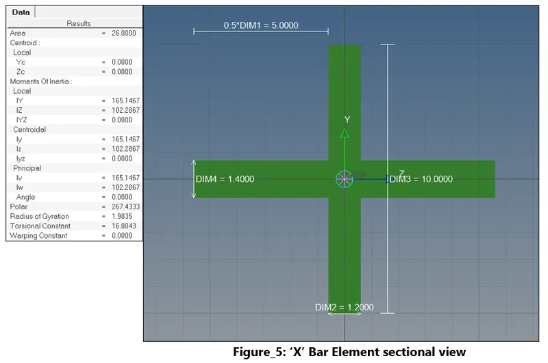
- Create property card for the beams and associate them with proper beam collectors.
- Create mass element at location d & e and using a spring element connect the two components together
RESULT: Final model is prepared according to the specifications with appropriate 1D elements.
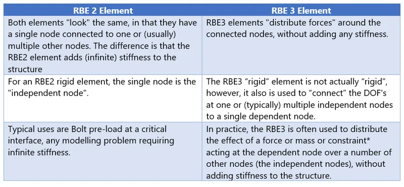
Key taleaway about Rigid elements:
A rigid element is a link from one node to one or more other nodes, where the motion of the node(s) is governed by the "degrees of freedom" you choose to connect.