Project-1: Powertrain for aircraft in runways
Project-1: Powertrain for aircraft in runways
Introduction: The project aims at studying different aspects of Aircraft working principles and its essential units that supports its working and important terminology related to it. It also aims at studying the tow-truck requirements and making a efficient electric powertrain design for the tow-truck.
OBJECTIVES OF THE PROJECT:
Study_1: Search and list out the total weight of various types of aircrafts
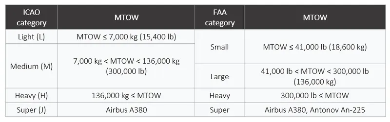
International Civil Aviation Organization (ICAO) classifies the aircrafts into different categories according to their Maximum Take-off Weight (MTOW) as below:
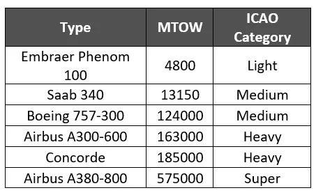
Let’s look at few types of such aircrafts:
Study_2: Is there any difference between ground speed and air speed?
Yes, both ground speed and air speed are different. While ground speed is the airplane’s speed relative to the surface of the Earth, airspeed – at least true airspeed – is its speed relative to the air it is flying in.

Ground Speed: For a reference point picked on the ground, the aircraft moves relative to the reference point at the ground speed.
Wind Speed: For a reference point picked on the ground, the air moves relative to the reference point at the wind speed. A positive velocity is defined to be in the direction of the aircraft's motion.
Airspeed: Airspeed is the vector difference between the ground speed and the wind speed. The important quantity in the generation of lift is the relative velocity between the object and the air, which is called the airspeed.
Study_3: Why is it not recommended to use aircraft engine power to move it on the ground at Airport?
Although many aircraft are capable of moving themselves backwards on the ground using reverse thrust (a procedure referred to as a power back), the resulting jet blast or prop wash might cause damage to the terminal building or equipment. Engines close to the ground may also blow sand and debris forward and then suck them into the engine, causing damage to the engine. A pushback is therefore the preferred method to move the aircraft away from the gate.
By using jet engines as an aircraft’s primary thrust for taxiing, airlines are expending huge amounts of jet fuel while still on the ground, which could be much better used for flying. With the Cost of Fuel being their single biggest expense, many airlines plan to adopt electric taxiing to save fuel and reduce environmental impacts.
Study_4: How an aircraft is pushed to runway when its ready to take off?
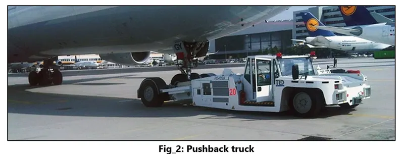
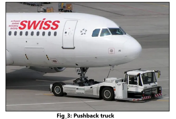
A so-called pushback truck reverses the aircraft into taxiing position, pushing it with a towbar attached to the nose-wheel strut. Or, in the most modern versions, by actually lifting the wheel. That speeds up coupling and decoupling.
Study_5: About take-off power, tire design, rolling resistance, tire pressure, brake forces when landing.
(A)Take-off power: Takeoff is the phase of flight in which an aerospace vehicle leaves the ground and becomes airborne.
In order to become airborne, the aircraft has to overcome the frictional force and drag force and achieve a take-off speed. After this the nose of the aircraft is tilted and the lift force overcomes the gravitational force of the earth.
The takeoff is the stage of the aircraft's movement from the takeoff run to safe speed `V_2 >=1.2*V_(s2` where `V_(s2` is the stall velocity for the aircraft and the height `H_2` simulated obstacle according to the accepted norms is 10.7 m . The basic parameter in determining the take-off and landing characteristics of the aircraft is the value of the minimum possible stall speed in the landing position.
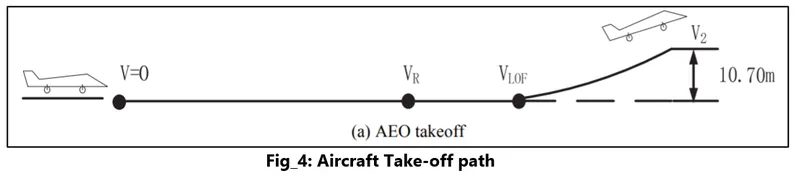
Let’s look at the power calculations:
Till lift-off:
`Power = (FORCE)*Velocity`; as this will vary continuously the peak power required will be at the take-off velocity, and the total force required by the aircraft will be the sum of drag force and the frictional resistance.
After lift-off, the aircraft will have to overcome the drag force and the weight and the velocity will be the change of vertical height with respect to the time. This is how the total power will be evaluated for the take-off.
(B) Tire design
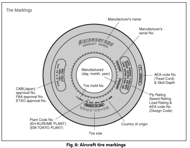
An aircraft tyre is designed to withstand extremely heavy loads while landing, take off, taxing, and parking. The number of wheels required for aircraft increases with the weight of the aircraft, as the weight of the aeroplane needs to be distributed more evenly.
An aircraft tyre is constructed for the purpose it serves.
- They support the weight of an aircraft while it is on the ground.
- It also provides the necessary traction for braking and stopping of an aeroplane.
- Tyre also helps to absorb the shock of landing and provide cushioning the roughness of takeoff, roll-out, and taxi operations.
Basic Structure
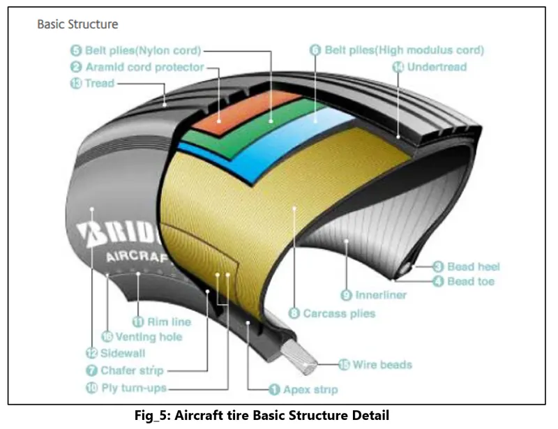
- Apex strip:A triangular piece of stiff rubber which is fitted onto the bead core to taper the rigid bead into the flexible body plies in the sidewall.
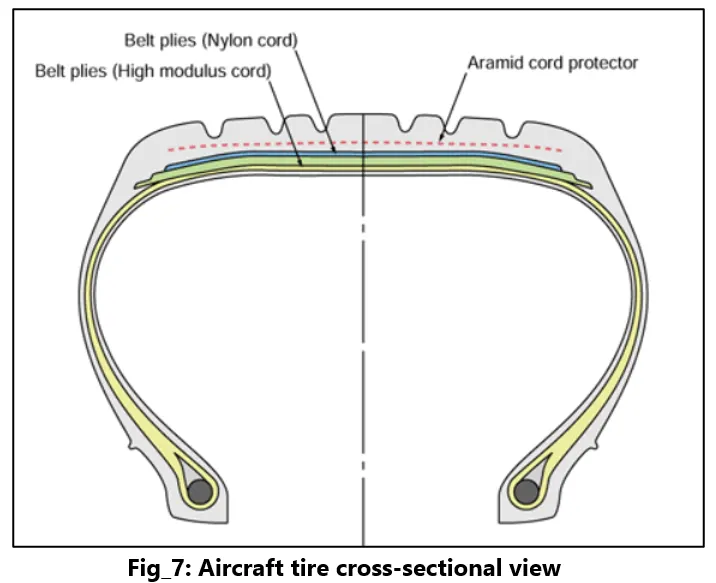
- Aramid cord protector:The tire is constructed with an aramid ply insert between the tread and the top belt to prevent damage to the tire belts.
- Bead heel:Outer edge of the bead.
- Bead toe:Inner edge of the bead.
- Belt plies (Nylon cord):Angled belt plies which serve to add strength to the tire especially in the tread area.
- Belt plies (High modulus cord):Belt plies which serve to add strength to the tire especially in the tread area.
- Chafer strip:Protective layer of rubber and fabric which prevents chafing between cord body plies and the wheel.
- Carcass plies:Layers of rubber-coated fabric plies which have the cords running radially from bead to bead. These provide the tire with strength in the sidewall area.
- Inner-liner:A sheet of low permeable rubber laminated to the inside of the first casing ply of a tubeless tire to insure retention of air when tire is inflated.
- Ply turn-ups:The turned-up ends of plies around the bead. Other plies lock the ends into place.
- Rim line:A line provided near the beads to allow inspection of how the tire fits with the rim.
- Sidewall:The side area of the tire located between the shoulder and the beads. Composed of rubber, it protects the carcass from damage.
- Tread:The functions of the radial tread are the same as those defined for the bias tire.
- Under-tread:A rubber layer provided for use in retreading the tire and which provides adhesion of tread to the tire carcass. Bridgestone makes this rubber layer thick enough to ensure a high number of retreads.
- Wire beads:Two wire bundles (one for each bead) which help to maintain the shape of the tire and anchor it securely to the rim.
- Venting hole:The hole through which gas is vented from inside the carcass plies.
(C) Rolling resistance:
Rolling resistance, sometimes called rolling friction or rolling drag, is the force resisting the motion when a body rolls on a surface.
`F=C_{rr}N`
`F`= force
`C_{rr}`= dimensionless rolling resistance coefficient
`N` = normal force
The coefficient of rolling friction is the indication of how great the rolling resistance is for a given normal force between the wheel and the surface upon which it is rolling. This ratio is based on the Standard Friction Equation.
Because of the various factors, the coefficient of rolling friction is usually determined experimentally.
The coefficient of rolling friction, μr, isn't a simple number as in the case of sliding friction for hard materials. Instead, it is proportional to the width of the wheel and inversely proportional to the radius. In the case of soft wheels and tires, μr the surface area of the tire on the ground is also a factor.
For a aircraft this number might vary depending on the type of tire, the runway conditions etc and would lie somewhere in the range of 0.02-0.01.
(D) Tire pressure
The typical airliner tire can handle a 38-ton load. It can meet the ground 500 times before needing a re-tread, a refresh it can take on seven times in its life. The key to their remarkable durability is maximizing the air pressure.
The high-flying rubber is typically inflated to 200 psi, roughly six times what you put in an automobile tire, and the tires on an F-16 fighter are pumped to 320 psi. “It's really pressurized air that's so strong,”
High inflation pressure and high deflection rates – 2.5 times greater than a car tire – allow relatively small tires to support the high loads of an aircraft.
(E) Landing Brake force
Stopping an aircraft landing at 180 mph requires a lot of braking force. To do this, the brake units are powered by the hydraulics system. An electrical signal is sent from the flight deck to hydraulic actuators near the main landing gear. Here, hydraulic fluid at 3,000 pound per square inch is used to force the brake unit against the wheel, thus slowing it down.
Another method of braking in fly by wire type aircrafts when the pilots press on the brake pedals, an electrical signal is sent to the brake unit on the wheel. Here, electrically powered actuators are used to press the carbon brake disc against the wheel, slowing it down.
The brake system on the 787 Dreamliner is controlled by the pilots pressing the tops of the rudder pedals under their feet, demanding the rate of braking which they require. This sends an electronic signal to the Left and Right Brake System Control Units (BSCUs).
These then send signals to the four Electronic Brake Actuator Controllers (EBAC) which control the rate of braking on the wheels. Each wheel has four Electric Brake Actuators (EBA), a kind of piston which presses against the carbon brake discs.
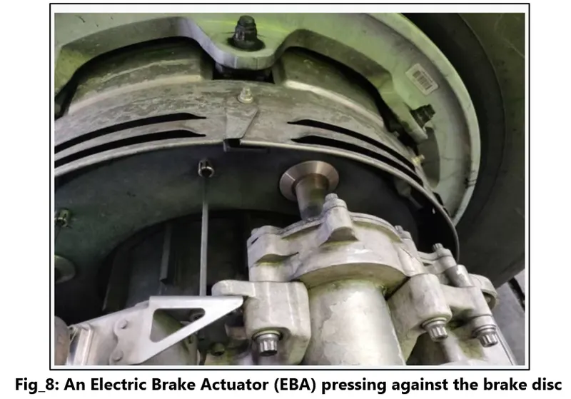
As these drive tabs are in contact with the inside of the wheel, they spin at the same speed. Depending on the brake manufacturer, there are either four or five of these rotors on each brake assembly.
The second part of the disks are the stators. These sit around each rotor and are fixed in place and thus don’t move. As the wheel turns, the rotors spin round inside the stators.
When the brakes are applied, the four EBAs apply pressure to the first stator. This in turn squeezes the stationary stators up against the spinning rotors and it’s this friction which slows the wheel down.
In addition to the brakes, there are two other systems which help slow the aircraft down on landing. The spoilers and the reverse thrust.
Spoilers
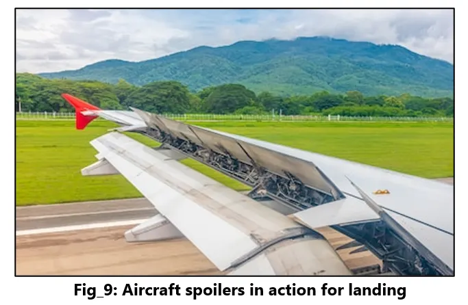
Have you noticed the large panels on the top of the wings raise up on touch down? These are the called the spoilers as they literally spoil the airflow over the wing. This dumps any remaining lift the wings are generating, allowing the wheels to take all the weight and achieve maximum efficiency from the brakes.
Reverse thrust
The final part of the braking process comes from reverse thrust. Just after we have touched down, we pull two levers on top of the thrust levers to engage the reverse thrust, a sort of “reverse gear” for jet engines.
With necessary assumptions, calculate the force and power required to push / pull an aircraft by a towing vehicle.
Assumptions:
- Assuming that there is no inclination and no high-speed winds
- And the towing speed of the aircraft to be 10Km/hr
- No cross-wind conditions
- Aircraft chosen for calculation Boeing 737, Tug Truck chosen T-80.
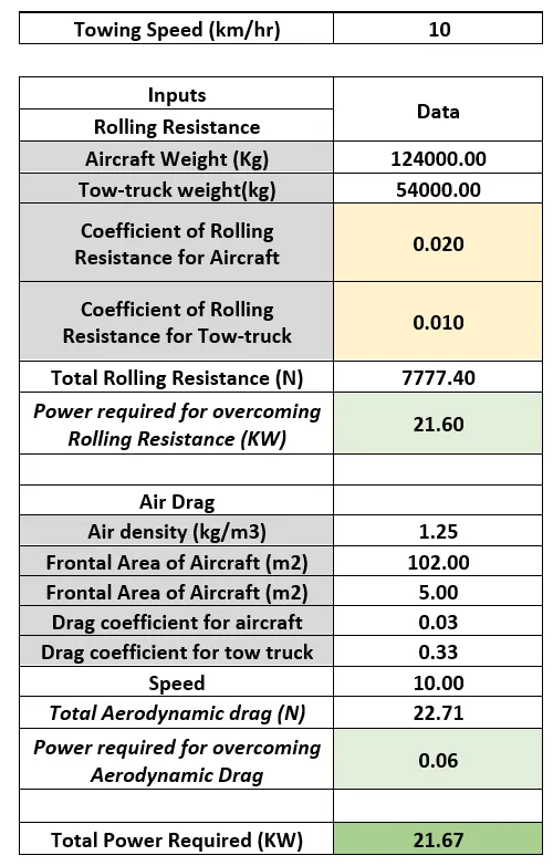
From these calculations we can see that we need a tow-truck which can overcome these requirements by producing High torque and can steer this aircraft safely onto its taxing path.
Study_6: Design an electric powertrain with type of motor, it’s power rating, and energy requirement to fulfill aircraft towing application. Estimate the duty cycle range to control the aircraft speed from zero to highest. Make all required assumptions. Prepare a table of assumed parameters. Draw a block diagram of powertrain.
Assuming the following parameters:
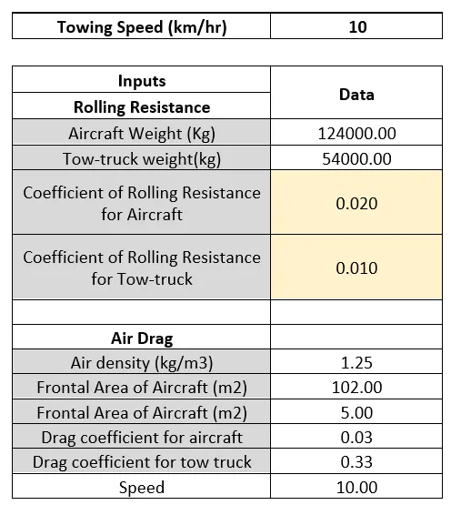
So, from the power calculations we understand that the Total force that should be generated by the tug-truck to tow the aircraft is 7800 Newtons. Hence at each wheel the truck should be able to produce a required Torque, lets calculate that.
Total force required to overcome the drag and rolling friction`F_(te) =7800 N`
Radius of each wheel = 25inches=0.63m
Now `F_(te)=T*G/r`
As we have a motor which is able to produce a large amount of Torque so we are not using gears but if we choose a motor whose max torque is less than we can use a gear for increasing the torque.
Hence, Total torque required =7800*0.63=4914 N-m=4.9 KN-m
So, assuming that each wheel produces same torque, the motor will have to provide a torque of 0.81KN-m torque at those 6 wheels.
We will choose a 35 kW BLDC motor.
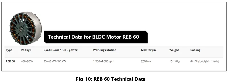
Now at 400 V it will be producing a continuous torque of 35kW, and our requirement is 21.6 kW. So, we need a chopper and a PWM (Pulse Width Modulation) and duty cycle for speed control.
So, for our requirement, `P_(ave)/P_(peak)=21.67/35=0.61`
Hence the duty cycle will be 61%. So, by varying the duty cycle from 40% to 50% and 61% we can reach the speed of `10(Km)/(hr` for the towing application.
The below block diagram indicates the powertrain design.
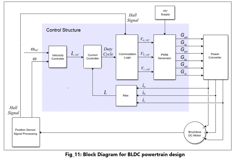
The BLDC Current Controller with PWM Generation block generates a pulse width modulation (PWM) signal and controls current in a brushless DC motor.
Let’s briefly look at how the motor will be controlled:
There are two ways in which the motor speed control can be done. One is using a buck converter to change the supply voltage or as shown above by changing the individual phase voltage in the commutation logic by having a PWM voltage source.
This type of control requires a hall sensor to sense the location of the rotating armature and then send the position to the controller and by using a commutation logic and a 3-phase inverter we keep the armature rotating by constantly changing the magnetic field. The commutation logic is shown below.
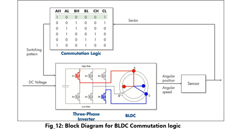
This is just a simplified version of the commutation logic control. Here we can observe that depending on the location of the rotor in each sector, the control logic switches the phase supply using the 3-phase inverter.
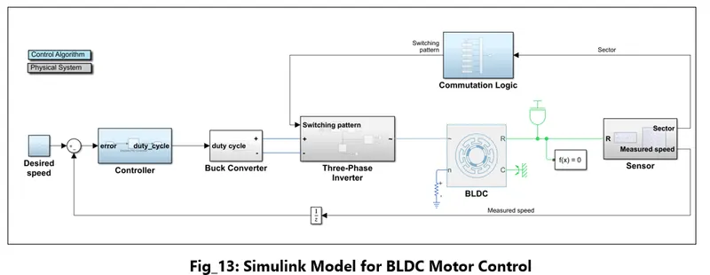
Using the above model, we can study the motor performance characteristics for the Aircraft Tow-truck application.
References:
http://www.littlebigtugcompany.co.uk/specs.htm
https://www.mgm-compro.com/products/30-50kw-electric-motors/