Week 9 - Attachment Feature Creation (Ribs & Screw Boss) - Challenge 1
Aim: Designing of Ribs and Screw bosses on a CATIA part and Draft analysis of a CATIA Component created using surface commands
Theory:-
Draft angle: A draft angle is a slant that is applied to each side of most features of an injection molded part. The angle, which is positioned to run toward the direction of a mold's pull and parting line, helps with releasing the part from the mold.
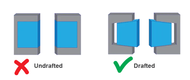
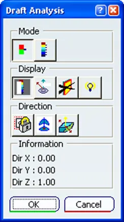
Draft analysis: The Draft Analysis allows the user to easily analyze a part for a proper draft angle. A Draft Angle describes the amount of taper for molded or cast parts perpendicular to the parting line. Find the Draft Analysis in the Tools tab. Draft Analysis is applicable for 3D part models.
Tool Axis Creation: -
In Molding, machine arrangement is given to open the mold along a direction which is known as Tooling Direction.
1. Likewise in our model, we first create a dummy tooling axis using one of 2 mostly used methods, i.e
> From a large circular contour
> From a large flat surface.
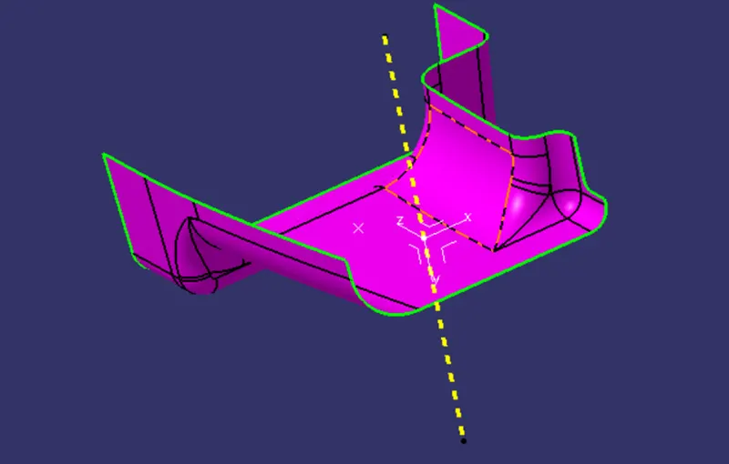
2. Then we take a plane and using that plane, we will create an intersecting geometry in order to trace the parts of the models which might be critical for the draft analysis following which we extend the surface which are at angles from the dummy tooling axis.
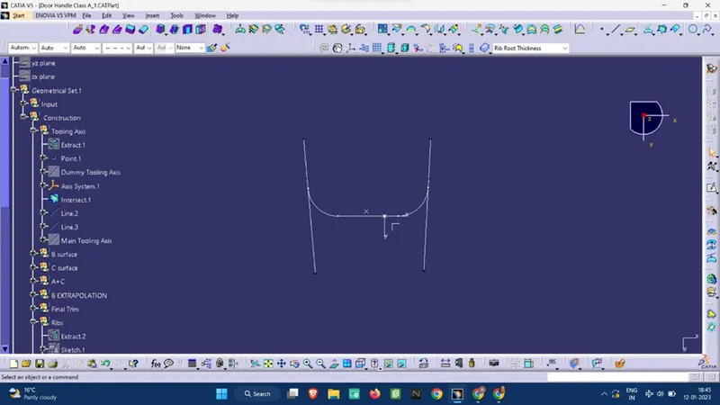
3. Now we create a Bisecting Line that bisects the other two lines thereby generating the main tooling axis.
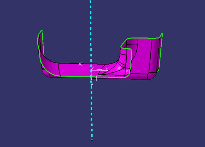
Thus we specify the tooling axis, also while selecting the tooling axis, we must check all the possible axes and choose the one with the least amount of complexity throughout the process of molding while checking the safest way for ejection of the product with less resistance.
Draft analysis:-
Standard Measurements:
Model Thickness: 2.5 mm
The minimum Draft angle provided: 3 deg angle
Class A surface Draft analysis:-
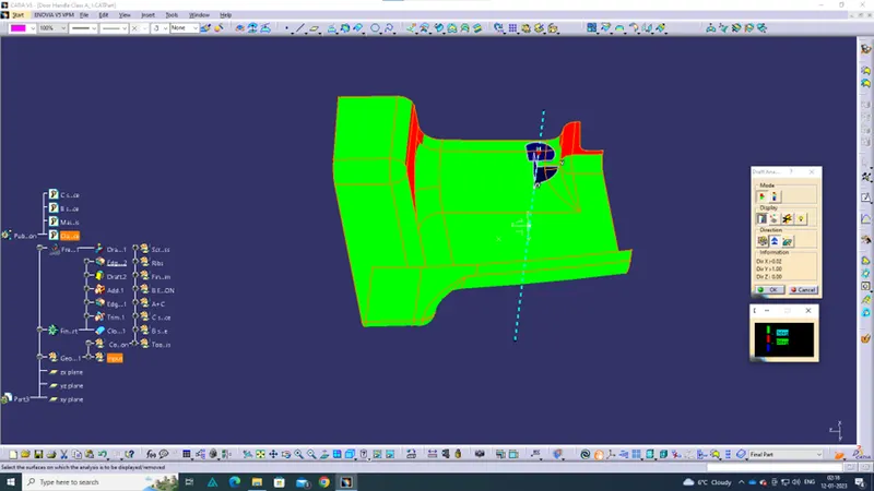
Final Body draft analysis:-
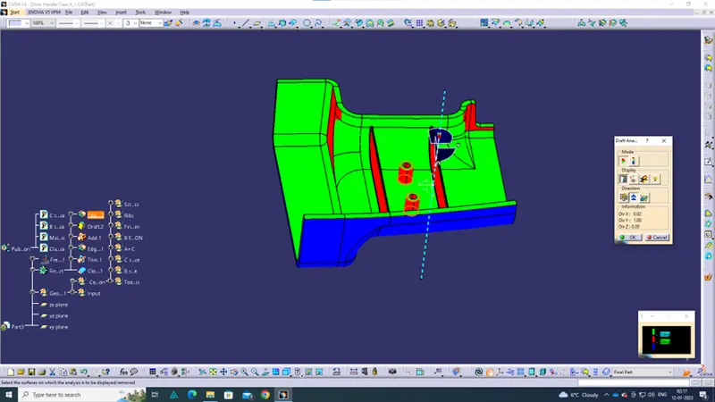
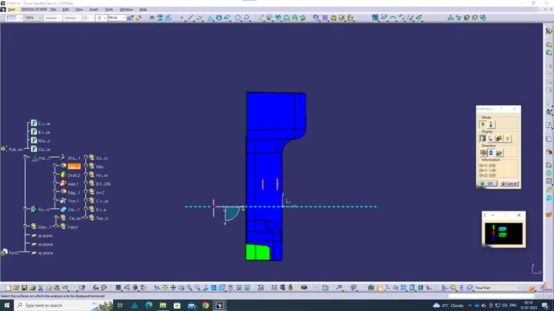
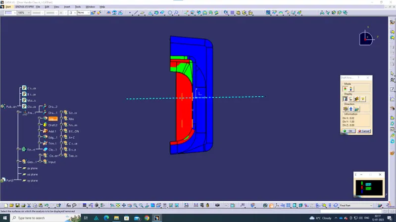
Note: The Blue region shows the draft surface is less than 3 deg and the red region shows that the surface draft is in between 0 to 3 deg.
Different view of the draft analysis:-
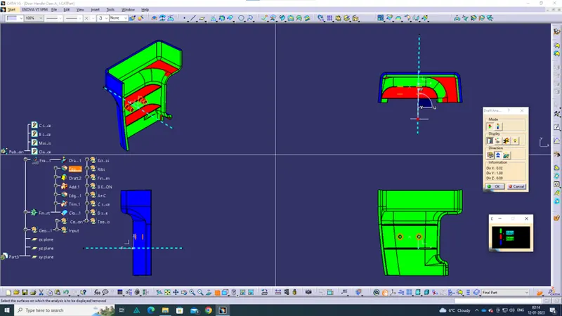
Front View: -
Bottom View:-
Side View: -
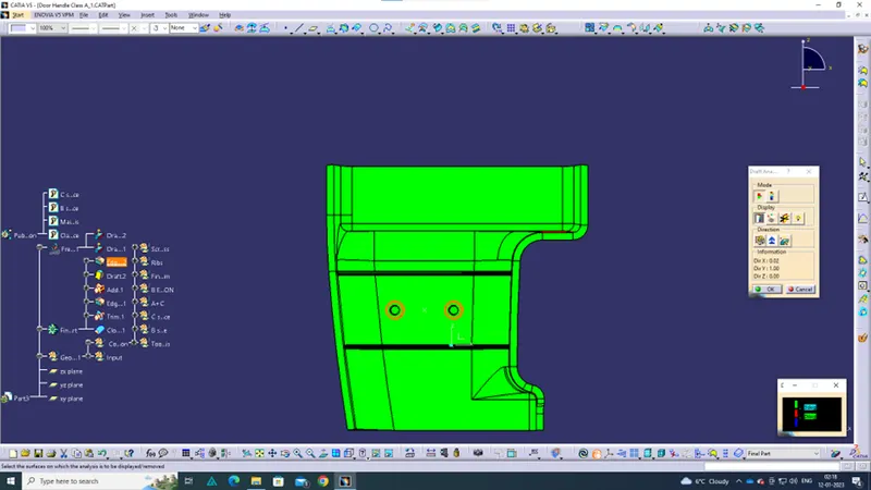
Note:
Green Surface: Denotes that the model satisfies the required draft angle
Blue Surface: Denotes that the model draft angle is below the required draft angle.
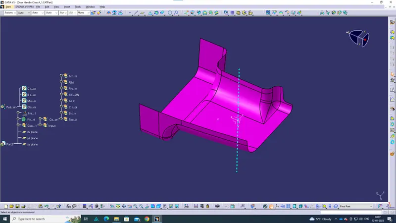
Different surfaces:-
Class A surface:
Class B surface:
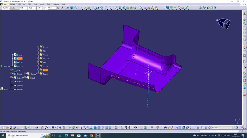
Class C surface:
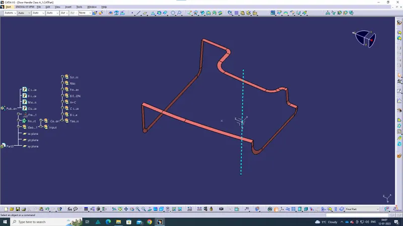
Part 2: Design of Ribs and Screw Bosses:-
1> Ribs:-
Introduction:-
Ribs: Ribs are thin, wall-like features typically designed into the geometry of a part to add internal support to walls or other features like bosses. In a similar fashion, gussets are support features that reinforce areas such as walls or bosses to the floor.
Design rules followed:-
Draft - 0.5 degrees on the walls of boss
Thickness at top >= 0.75mm
Height = 5*thickness of the component
Wall Thickness= 0.4* Thickness of the component
Radii of fillet = 0.25mm maximum radii.
Calculations:-
Height -> 5*2.5=12.5mm
Wall Thickness -> 0.4*2.5= 1 mm
Since The distance between the ribs are not given,
I have taken 25 mm distance between the two ribs.
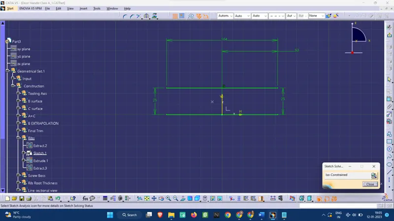
Now we add another body and use the pad command to generate the thickness:-
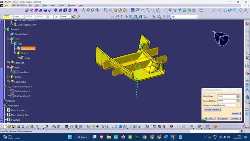
Now we use the Union Trim Boolean command to trim the excess part.
Rib Root Thickness:-
By taking a section and drawing tritangent circle we get the rib root thickness:-
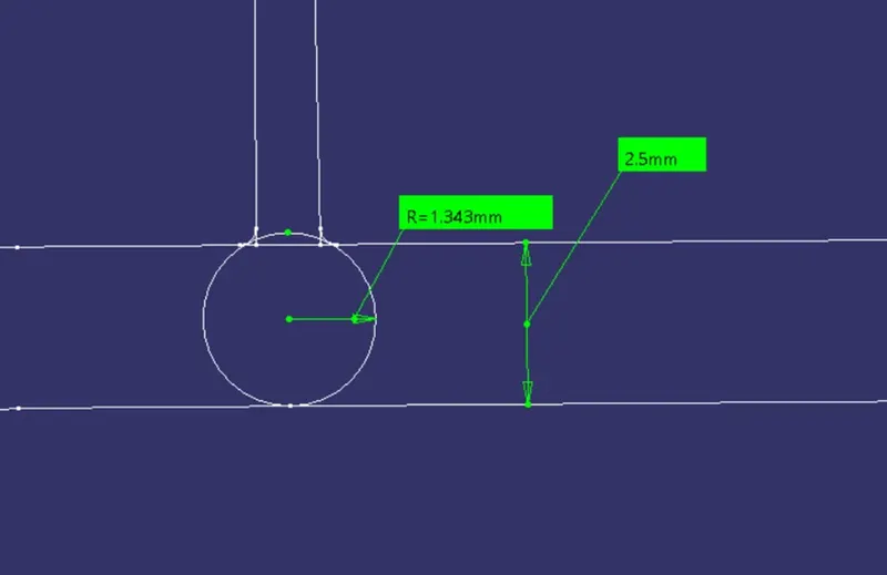
Note as the rib and other bodies are added to the final body and not assembled hence a straight line can be seen depicting the thickness of the part.
2> Screw Boss Design:-
Introduction:-
Screw Bosses: Boss features are commonly found in injection molding designs. They are used to aid in the assembly of molded parts by providing a channel for a screw. Designing plastic screw bosses is fairly straightforward but there are a few considerations to ensure a strong connection between parts and mitigate cosmetic defects.
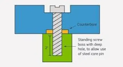
Design Rules Followed:-
Draft - 0.5 degrees on the walls of boss
Thickness - Typically 40%* of the nominal wall at the base.
Wall Thickness= 2-2.5 times the inner dia.
Height to Diameter Ratio - 3:1
Radii - 0.25mm maximum radii.
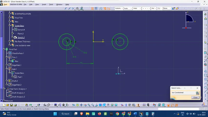
Calculations:-
Height to Diameter Ratioà 8/3 =2.667 mm which is < 3mm
Wall Thicknessà 3*2=6mm outer dia
As the distance was not given, hence taken a nominal distance of 20mm between the centers.
Conclusion: Draft analysis is a very essential tool for manufacturing a plastic product using Core and cavity manufacturing techniques, hence draft angle should always be provided appropriately.
Support features are to be added by applying all the design rules since it will help the final part to gain the sufficient support it needs during the injection molding process.