Week 8 - Simulating Cyclone separator with Discrete Phase Modelling
Week 8 - Simulating Cyclone separator with Discrete Phase Modelling
Introduction:-
The centrifugal force produced by a spinning gas stream is used by cyclones to separate the particles from the carrier gas. They are perfect for use as pre-cleaners for more expensive final control devices like bag houses or electrostatic precipitators due to their straightforward design, low initial cost, and almost maintenance-free operation. Cyclones excel in high temperature and pressure environments because to their robust construction and flexible component materials.
For particles larger than 5 m, cyclone collection efficiency can exceed 99% and can be used at very high dust loadings.
Large particle removal is done with cyclones for both process usage and reducing air pollution.
The removal of coal dust from a power plant, the usage as a spray drier, or the use as a gasification reactor are examples of applications in harsh environments.
In order to evaluate the design and performance of a cyclone, engineers are often interested in two characteristics. These variables are the pressure drop through the cyclone and particle collecting efficiency. It is crucial to anticipate cyclone efficiency accurately since an inaccurate prediction might lead to an ineffective cyclone separator design. The pressure decrease inside the cyclone as well as the properties of the flow field and particle trajectories may all be accurately predicted using CFD.
This study also examines the cyclone efficiency predictions of four distinct empirical models:
1.Lapple,
2.Koch and Licht,
3.Li and Wang, and
4.Iozia and Leith.
Following that, experimental data from the literature for various inlet flow rates, pressures, and temperatures is compared with the modelling findings.
1. Lapple
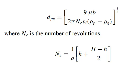
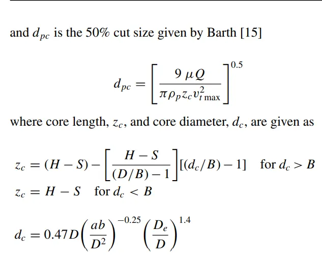
Without taking into account flow resistance, the Lapple model was established based on force balance. Lapple made the supposition that a particle entering the cyclone is dispersed uniformly over the inlet hole. In the cyclone, the particle that passes from the half-width entrance to the wall is gathered with a 50% efficiency. Lapple created a semi-empirical relationship to determine a 50% cut diameter, dpc, and it is
2. Koch and Licht
The Koch and Licht collection hypothesis identified the dispersion of gas residence periods inside cyclones and the intrinsically turbulent character of cyclones. Koch and Licht made the following additional assumptions for describing particle motion in the entrance and collecting regions:
• The tangential velocity is linked to the radius of the cy clone by: u Rn = constant.
• The tangential velocity of a particle is equal to the tangential velocity of the gas flow, i.e., there is no slip in the tangential direction between the particle and the gas.
The grade efficiency is determined by a force balance and an equation for the collection of particles.
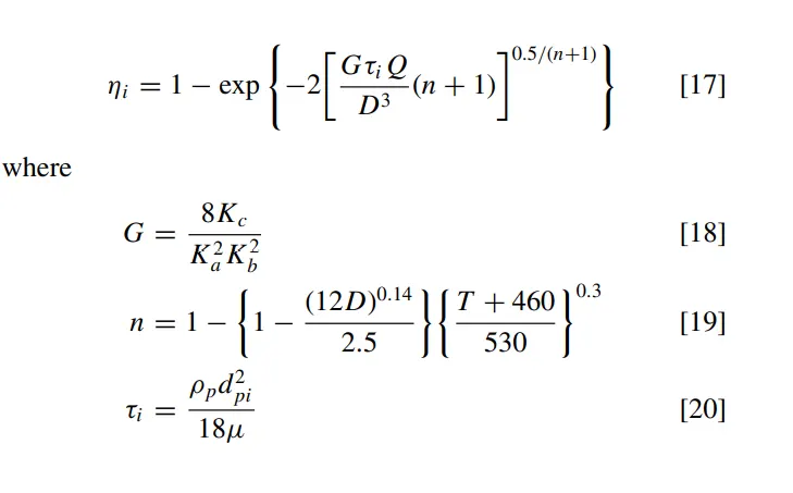
G is a factor related to the configuration of the cyclone, n is related to the vortex and τ is the relaxation term.
3. Li and Wang
The Li and Wang model takes into account turbulent diffusion at the cyclone wall as well as particle bounce or re entrainment. It is possible to represent the particle distribution in the cyclone analytically in two dimensions. The following presumptions served as the foundation for the Li and Wang model:
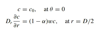
• For uncollected particles inside the cyclone, the radial particle velocity and the radial concentration profile are not constant. • Boundary conditions taking into account the turbulent diffusion coefficient and particle bounce re-entrainment on the cyclone wall are:
• The tangential velocity is related to the radius of cyclone by: u Rn = constant.
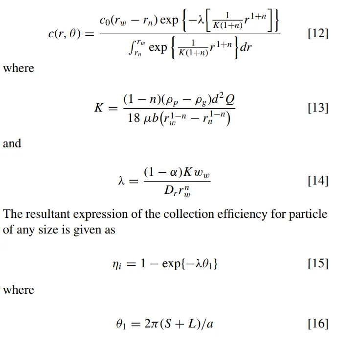
The concentration distribution in a cyclone is given as:
4. Iozia and Leith
The Barth Model, which was created based on force balance, was updated by Iozia and Leith.
A particle transported by a vortex is said to be subject to two forces: a centrifugal force, Z, and a flow resistance, W. One may determine the collecting effectiveness I of particle diameter dpi from
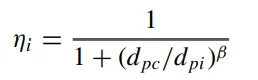
β is an expression for slope parameter derived based on the
statistical analysis of experimental data of a cyclone with D = 170
0.25 m given as
Mesh stats:
1. Main element size: 5mm
2. Method = Cartesian method
3. No. of elements= 427361
After meshing the model, pick generate mesh to create the basic mesh. However, since mesh refinement affects how many particles enter the inlet, it is preferable to refine the mesh suitably.
The analysis is done for 500 iterations.
- Diameter of the particles = 1 micrometers
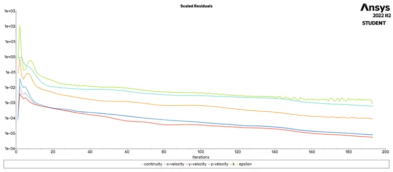
The scaled residuals plot :
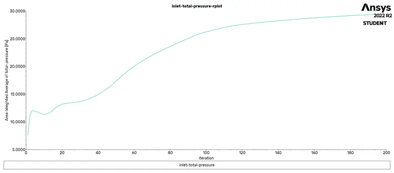
Inlet Pressure
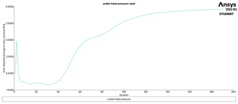
Outlet Pressure
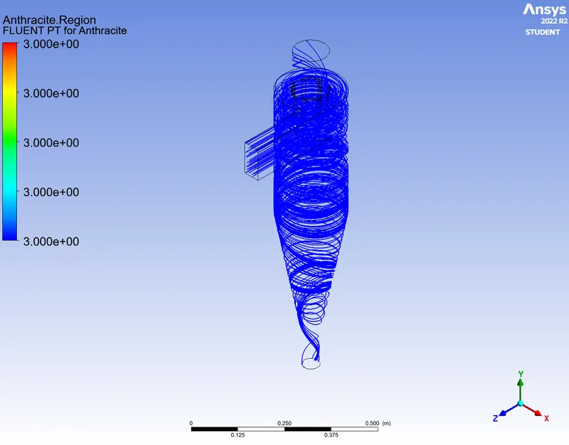
Track of particles (in Video format)
Link of the video:-
Fluent PT For Anthracite
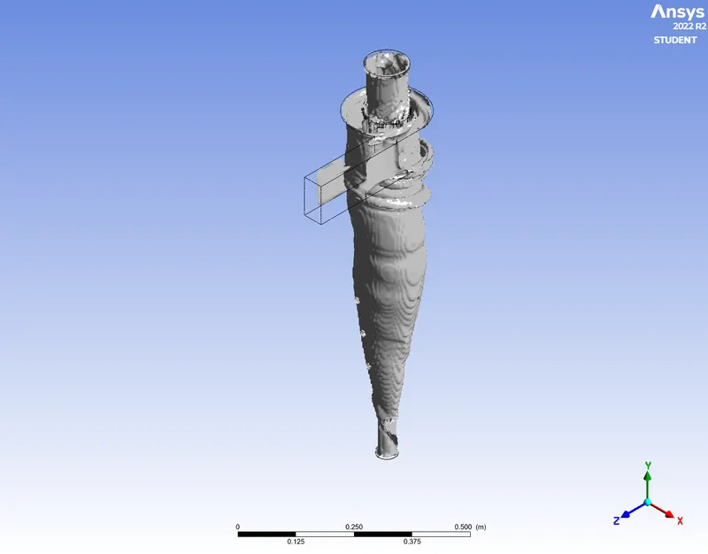
Votex Core Strength region (Swirling Trength)
Numbers of particles trapped and escaped

Pressure Drop
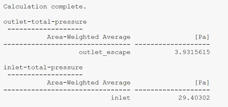
According to the Problem Statement,
Calculation of Separation Efficiency & Pressure Drop In this case are:-
1. Separation efficiency:-
separation efficiency = (Number of particles trapped / Number of particles tracked ) * 100
i.e Here, (312/378)*100 = 82.54%
2. Pressure Drop:-
pressure drop = inlet Pressure - outlet pressure
here, (29.403 - 3.931)Pa = 25.472 Pa
Case - 2
Diameter of Particles = 3micrometer & Velocity = 3m/s
Plots:-
Residuals Plots:-
Inlet Pressure
Outlet pressure
Fluent Pt For Anthracite
Swirling Strength
particles Trapped & Escaped

Pressure Drop
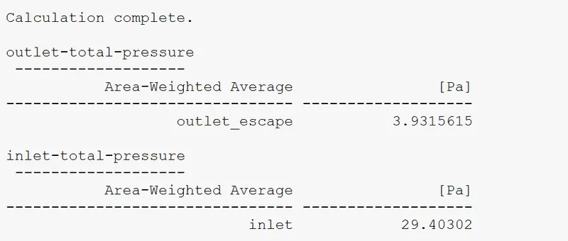
Video Track of Particles
Link of the video
Calculation of separation efficiency & Pressure Drop
1. Separation efficiency :-
S.E = (Number of Particles trapped / particles tracked ) * 100
here, (312/378) * 100 = 82.54%
2. Pressure Drop:-
Pressure Drop = Inlet Pressure - Outlet Pressure
here, (29.403-3.931)Pa = 25.472 Pa
Case 3 - Diameter of Particle = 5 micrometer & Velocity = 3m/s
Plots:-
Residuals Plots:-
Inlet pressure
Outlet pressure
Fluent Pt for Anthracite
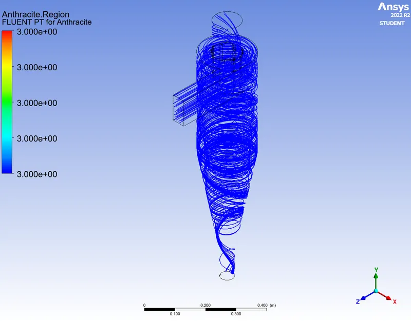
SWirling Strength
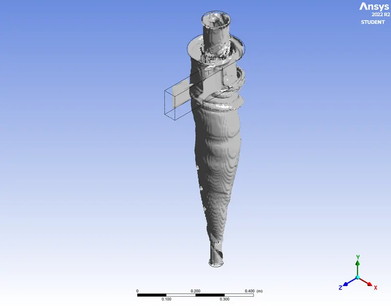
Particles trapped and Tracked

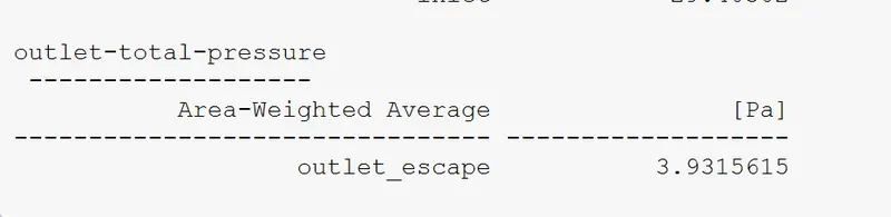
Pressure Drop (inlet - Outlet)
inlet pressure
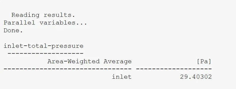
outlet pressure
Video link of the particles tracked
Calculation of Separation efficiency & Pressure Drop
1. Separation efficiency :-
Separation efficiency = (Number of particles trapped / Number of particles tracked ) * 100
here , = (267 / 378) * 100 = 70.63%
2. Pressure Drop
here, (29.403 - 3.931)Pa = 25.472 Pa
Case = 4
Diameter of Particles = 5 micrometer & Velocity = 1 m/s
Plots:-
Residuals Plots:-
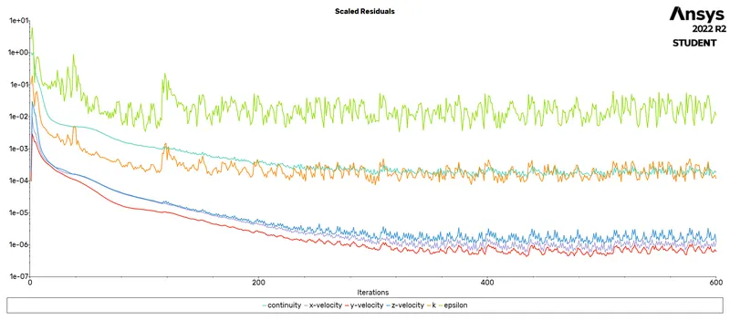
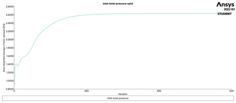
Inlet Pressure
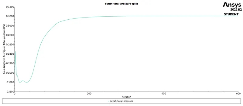
Outlet Pressure
Fluent Pt for Anthracite
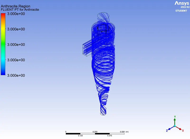
Swirling Strength
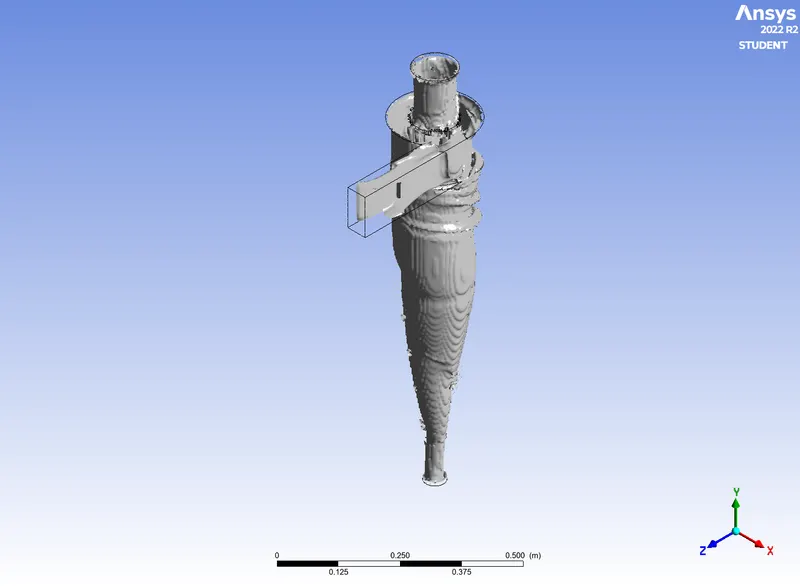
Particles trapped & Tracked

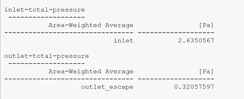
Pressure Drop
Video link of the particles tracked:-
Calculation of Separation efficiency & Pressure Drop
1. Separation Efiiciency :-
Separation efficiency = (Number of particles trapped / Number of particles tracked) * 100
here , S.E = (305/387) * 100 = 80.68%
2. Pressure Drop:-
Pressure Drop = (Inlet Pressure - Outlet Pressure)
here , (2.635-0.320)Pa = 2.315 Pa
Case = 5
Particle diamter = 5 micrometer & velocity = 5m/s
Plots
residuals Plots
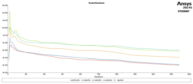
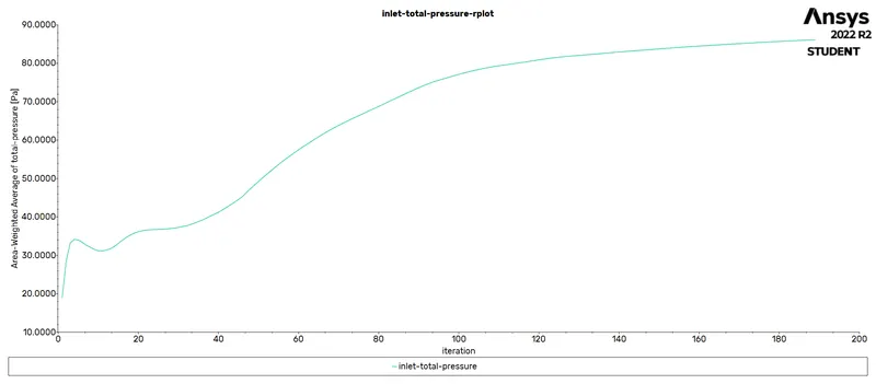
Inlet Pressure
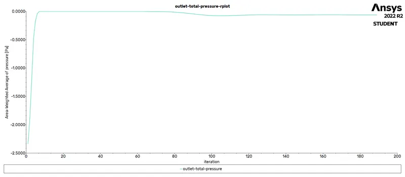
Outlet Pressure
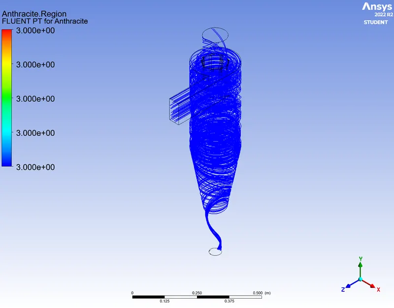
Fluent Pt For Anthracite
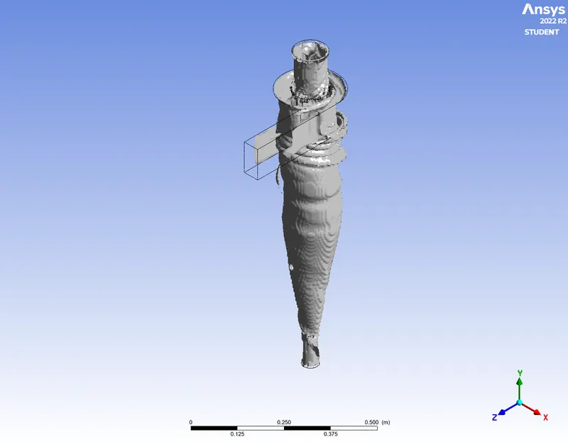
Swirling Strength
Number of particles trapped and Tracked

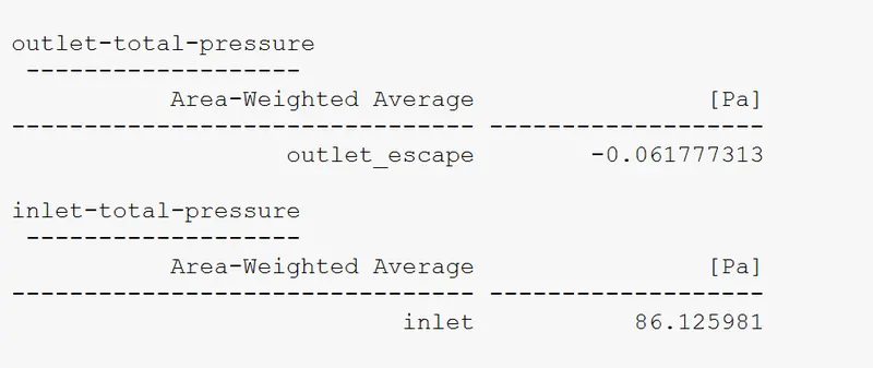
Pressure Drop
Video link of the particles tracked
Calculation of Separation efficiency & Pressure Drop
1. Separation efiiciency
Separation efficiency = (Number of Particles trapped / Number of Particles tracked) * 100
here , S.E = (289/378) * 100 = 76.45%
2. Pressure Drop
Pressure Drop = (Inlet Pressure - Outlet Pressure)
here, (86.125-(-0.0617) Pa = 86.1867 Pa
Final results Tabulation
Cyclone Separator Efficiency
| Size of the Particle | Velocity of the particle | No. of Particles Tracked | No. of Particles trapped | No. of particles escaped | cyclone separator efficiency |
| 5 micrometer | 1 m/s | 378 | 305 | 73 | 80.68% |
| 5 micrometer | 3m/s | 378 | 267 | 111 | 70.63% |
| 5 micrometer | 5m/s | 378 | 289 | 81 | 76.45% |
| 3 micrometer | 3m/s | 378 | 312 | 66 | 82.54% |
| 1 micrometer | 3m/s | 378 | 312 | 66 | 82.54% |