Week 9 - Parametric study on Gate valve.
Week 9 - Parametric study on Gate valve.
CHALLENGE FOR GATE VALVE SIMULATION:
AIM:- For this challenge, you will have to perform a parametric study on the gate valve simulation by setting the opening from 10% to 80%.
- Obtain the mass flow rates at the outlet for each design point.
- Calculate the flow coefficient and flow factor for each opening and plot the graph.
- Discuss the results of the mass flow rate and flow coefficient.
THEORY
WORKING
A parametric study requires the following:
- Design Objective is set to Parametric Dimensions
- Parameters nominated for use in the simulation
- Parameter ranges identified
- Design criteria specified
- Various configurations generated
We can assess our simulation once the settings have been produced. After we are happy with the outcomes, we may adjust the parameters or design limitations further. We can promote a configuration back to the model as a CAD edit if you've decided that it meets our design requirements.
Flow Coefficient:
The flow coefficient of a device is a relative measure of its efficiency at allowing fluid flow. It describes the relationship between the pressure drop across an orifice valve or other assembly and the corresponding flow rate. Mathematically the flow coefficient Cv (or flow-capacity rating of the valve) can be expressed as:
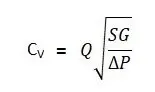
where,
Q is the rate of flow (expressed in US gallons per minute),
SG is the specific gravity of the fluid (for water = 1),
ΔP is the pressure drop across the valve (expressed in psi).
10pa=0.00145038psi
In more practical terms, the flow coefficient Cv is the volume (in US gallons) of water at 60 °F that will flow per minute through a valve with a pressure drop of 1 psi across the valve. The use of the flow coefficient offers a standard method of comparing valve capacities and sizing valves for specific applications that are widely accepted by the industry. The general definition of the flow coefficient can be expanded into equations modeling the flow of liquids, gases, and steam using the discharge coefficient.
Flow Factor:
The metric equivalent flow factor (Kv; commonly used in Europe and Asia) is calculated using metric units:
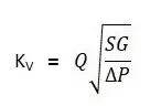
Kv can be calculated from Cv using the equation as given below:
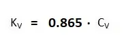
The Kv factor of a valve indicates "The water flow in m3/h, at a pressure drop across the valve of 1 kgf /cm2 when the valve is completely open.
Geometry:
Import the gate valve file into space claim
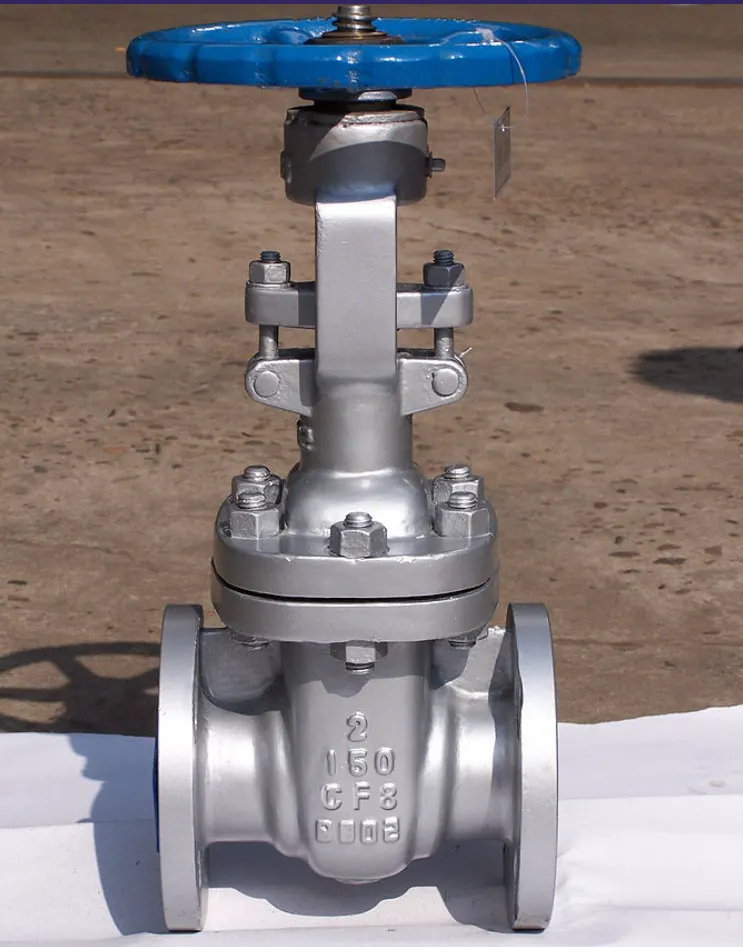
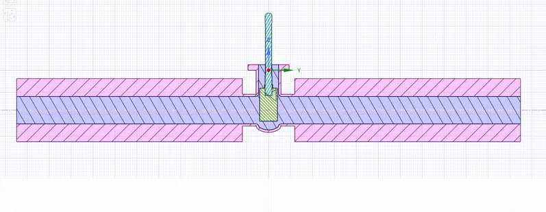
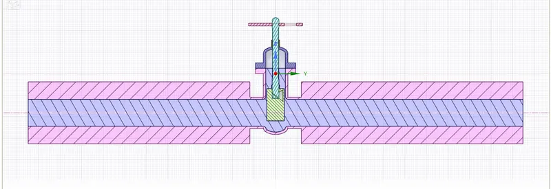
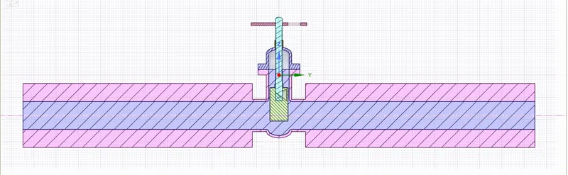
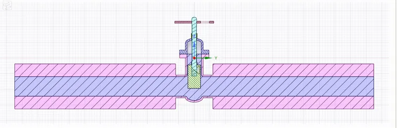
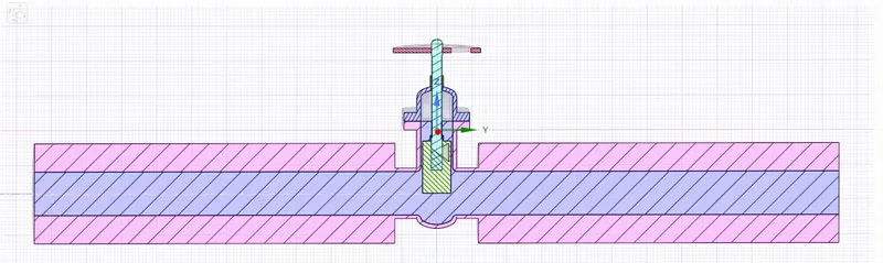
The model that was examined in Ansys Fluent is shown above. It has all of the characteristics of a gate valve. The Handwheel, Spindle, Bonnet, Gate Disc, and Bottom Part make up the gate valve. The valve is completely closed at first. For each design point of the parametric research, we must raise the lift of the gate disc. The lift of the Gate Disc is parametrized using the parameter option. The "move" command in Ansys Spaceclaim is used to provide the lift, and then the fluid volume is extracted. To generate the pipe shape, we utilise the "pull" command.
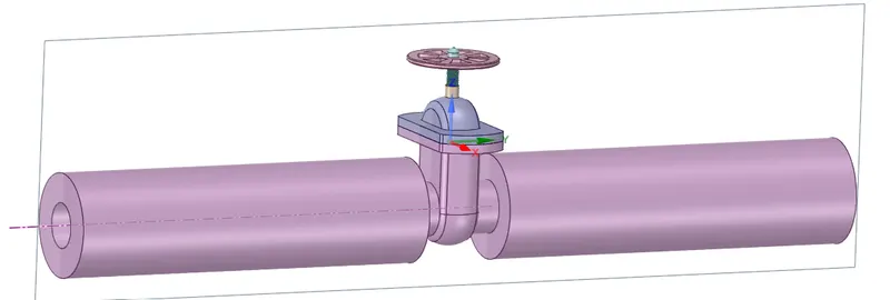
Initial Lift
Hide the "Bottom " Part , so we can claerly see the "Gate Disc".
- Then Select "Gate Disc" component and move it in upward direction by "10 mm" lift.
- To analyze the flow and its effects, we must allow the flow, and for that we have given "10 mm" lift to the "Gate Disc".
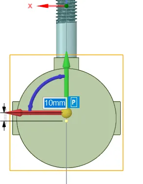
- Here we can see the green color arrow in upward direction, which shows the movement of "Gate Disc" in positive Z-Direction.
- Also we can see the symbol of "P".
- This symbol "P" is used to parametize the lift of the "Gate Disc".
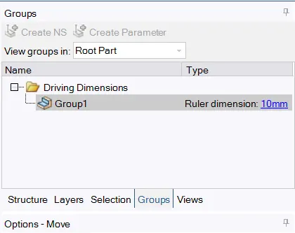
- After selecting the symbol "P", it turns in Grey color, and message shows that a Group has been vreaated for lift.
- Created group for lift parameter shown in above image.
- On the Left Side, in Tree Structure,if we see the group options, we can see created group and the amount of parameter, which has been set 10 mm lift.
- We can simply change the value of parametrs from there directly.
Lift adjustments:
Case-1: Lift adjustment=10mm in positive z direction.
Case-2: Lift adjustment=20mm in positive z direction.
Case-3: Lift adjustment=30mm in positive z direction.
Case-4: Lift adjustment=40mm in positive z direction.
Case-5: Lift adjustment=50mm in positive z direction.
Fluid Volume Extraction
update the volume body in context
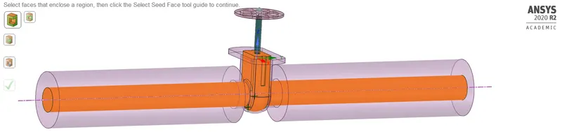
supress all other components other than fluid volume
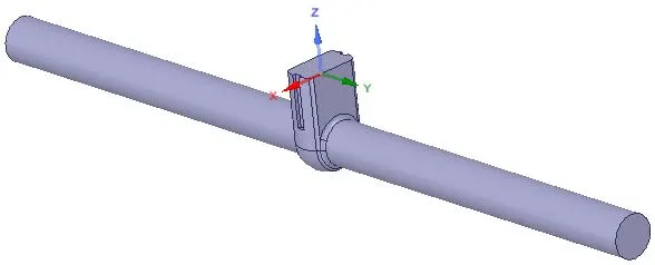
Mesh:
First name inlet and outlet
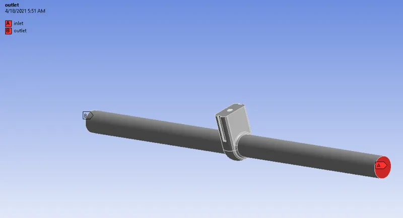
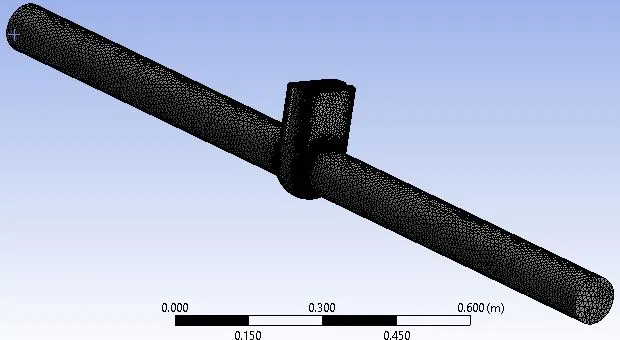
Computational Mesh
We use the default computational mesh. Element size = 10 mm.
Set up:
1. Solver: Steady
2. Type: Pressure Based
3. Gravitational Acceleration:
- X: 0
- Y: 0
- Z: -9.81 m/s2
4. Turbulence Model: Realizable k- omega with SST model
5.Cell Zone Condition:
- Fluid: Water
6. Material Specifications:
- Material: water-liquid (H2o)
- Density: 998.2 Kg/m3
- Viscosity: 0.001003 Kg/m-s
6. Boundaries:
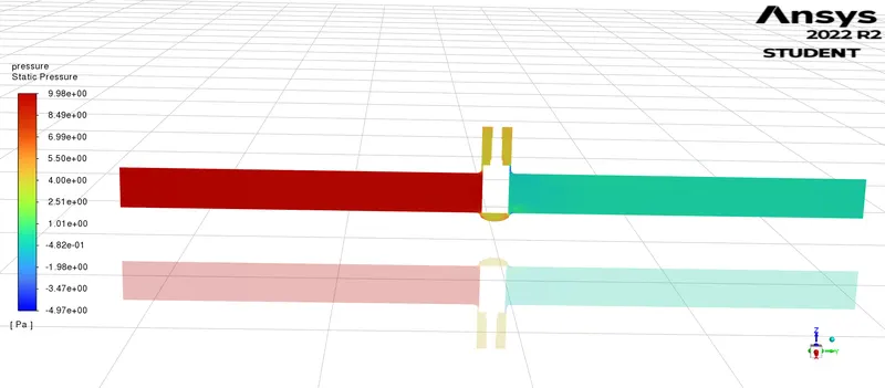
- Inlet: Pressure = 10 Pa(Gauge Pressure)
- Outlet: Pressure= 0 Pa (Gauge Presssure)
7. Solution Methods: Coupled
8. Initialization:
- Method: Standard Initialization from the Inlet
- Number of Iteration: 600
So, for Reynolds No,
ρ=998.2Kg/m3
V = 0.14145488 m/s
D = 0.1 m
Re=(ρ⋅V⋅D)/μ
= [998.2*0.1415488*0.1]/0.001003
= 14087.14
- Here, Reynolds No is 14087.14, which is more than 2000.
- So the flow is turbulent.
- So the viscous model will be K-omega.
- After initialization, Report Definitions for the report of Mass Flow Rate at the Outlet is created.
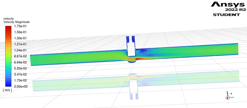
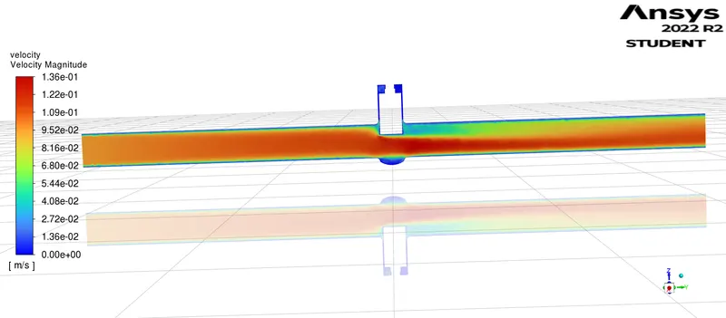
- Also Contours for Velocity Magnitudes is created.
- Animations for the flow of water inside Gate Valve based on Contours is created.
- But here, we have given Pressure Inlet, instead of Velocity Inlet. So knowing the velocity of the flow for correct Reynolds No. is required.
- So, to know the velocity of the flow, we have to go for initializing the solution.
- So, go to Solution, and select Standard Initialization, and Initialize from Inlet.
- After initialization, we can get the correct velocity and calculate the Reynolds No. and from that, we can decide for the appropriate viscous model.
OUTPUT
A.) PARAMETRIC STUDY OF MASS FLOW RATE
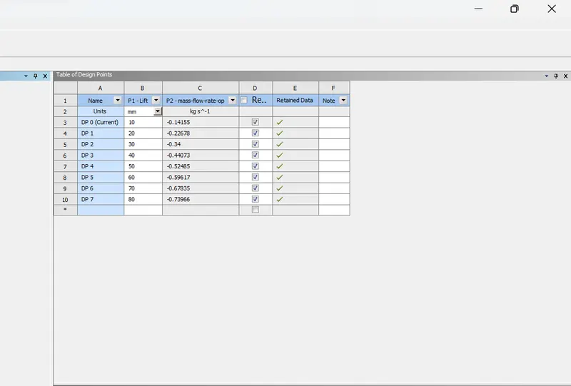
CASE - 1 , LIFT = 10MM
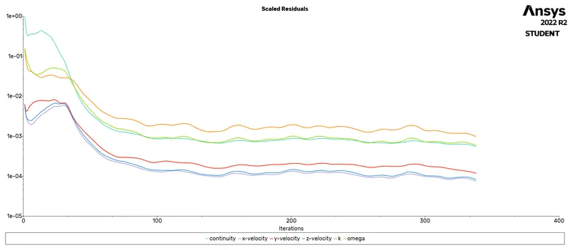
RESIDUALS
MASS FLOW RATE PLOT
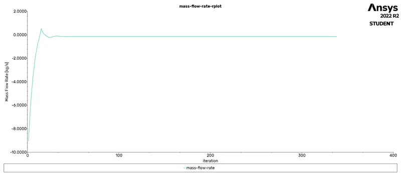
VALUE OF MASS FLOW RATE

VELOCITY CONTOUR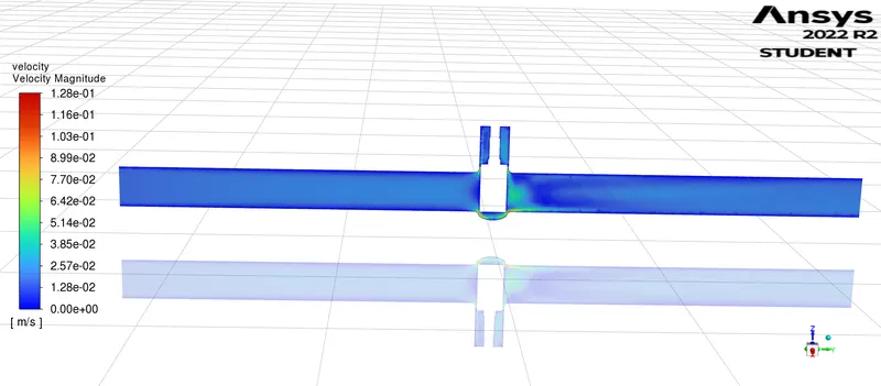
PRESSURE CONTOUR
CASE - 2 , LIFT = 20MM
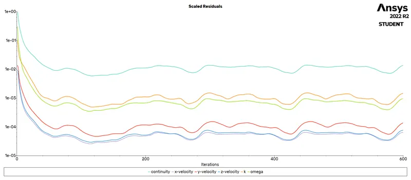
RESIDUALS
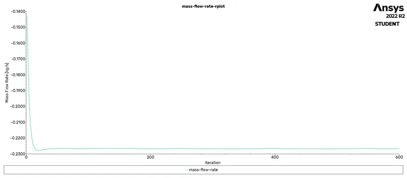
MASS FLOW RATE PLOT
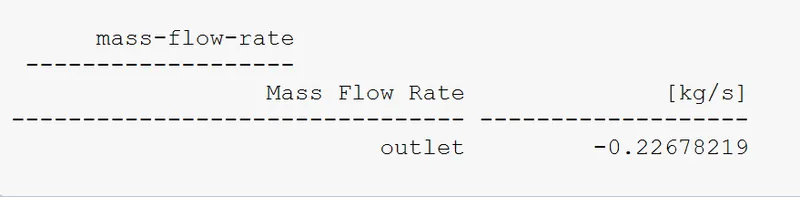
VALUE OF MASS FLOW RATE
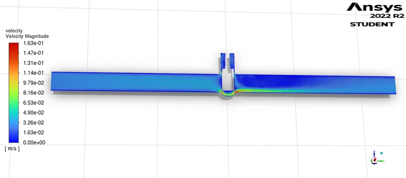
VELOCITY CONTOUR
PRESSURE CONTOUR
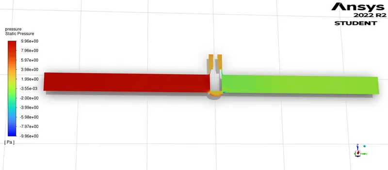
CASE - 3 , LIFT = 30 MM
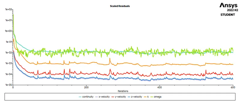
RESIDUALS
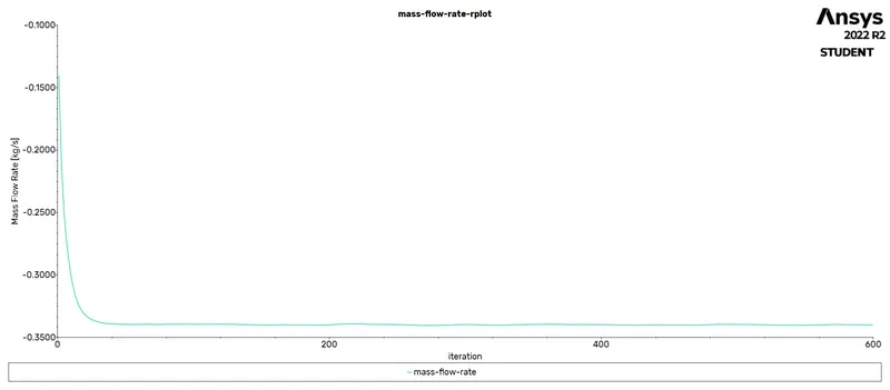
MASS FLOW RATE PLOT
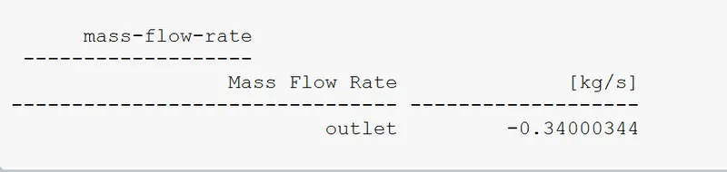
VALUE OF MASS FLOW RATE
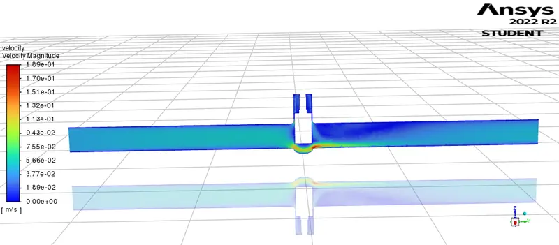
VELOCITY CONTOUR
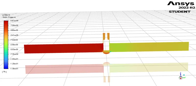
PRESSURE CONTOUR
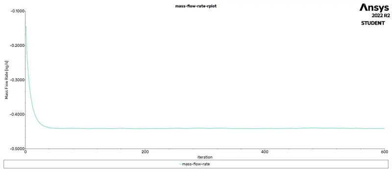
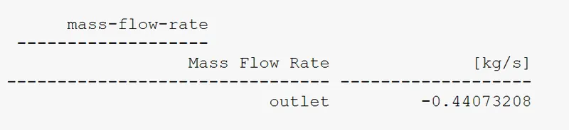
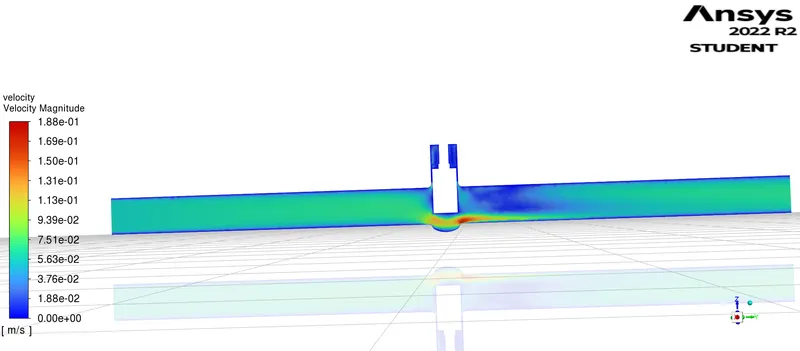
CASE - 4 , LIFT = 40MM
RESIDUALS
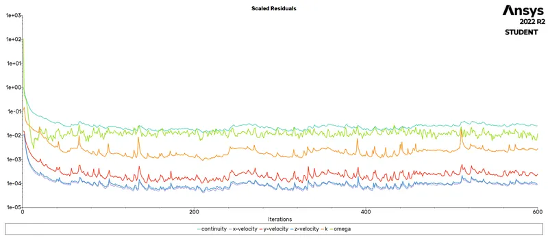
MASS FLOW RATE
VALUE OF MASS FLOW RATE
VELOCITY CONTOUR
PRESSURE CONTOUR
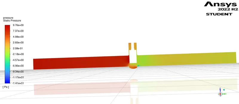
CASE - 5 , LIFT = 50MM
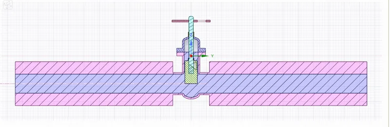
RESIDUALS
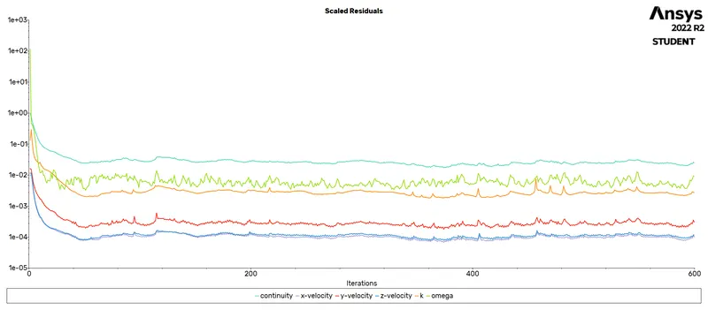
MASS FLOW RATE
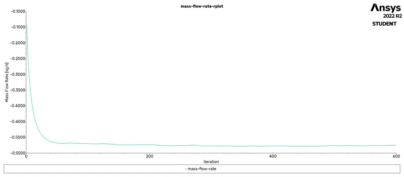
VALUE OF MASS FLOW RATE
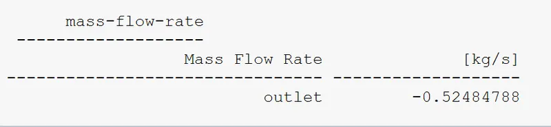
VELOCITY CONTOUR
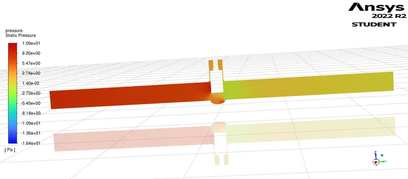
PRESSURE CONTOUR
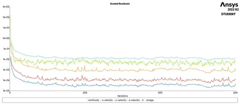
CASE - 6 , LIFT = 60MM
RESIDUALS
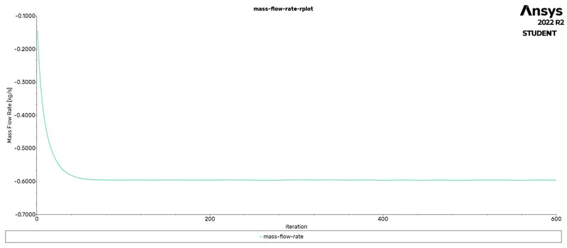
MASS FLOW RATE
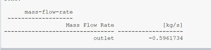
VALUE OF MASS FLOW RATE
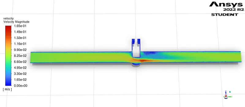
VELOCITY CONTOUR
PRESSURE CONTOUR
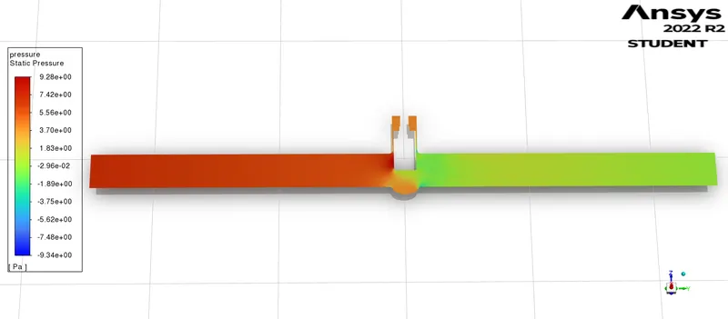
CASE - 7 , LIFT = 70MM
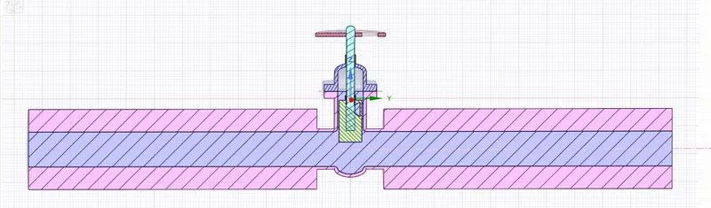
RESIDUALS
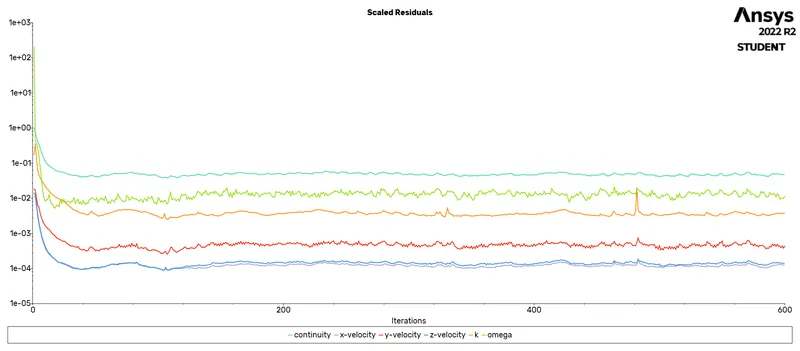
MASS FLOW RATE
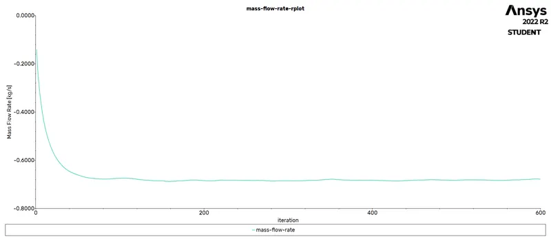
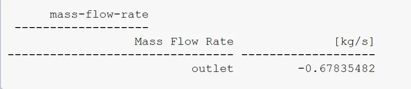
VALUE OF MASS FLOW RATE
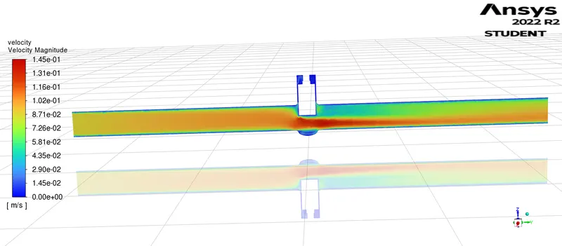
VELOCITY CONTOUR
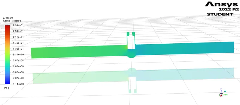
PRESSURE CONTOUR
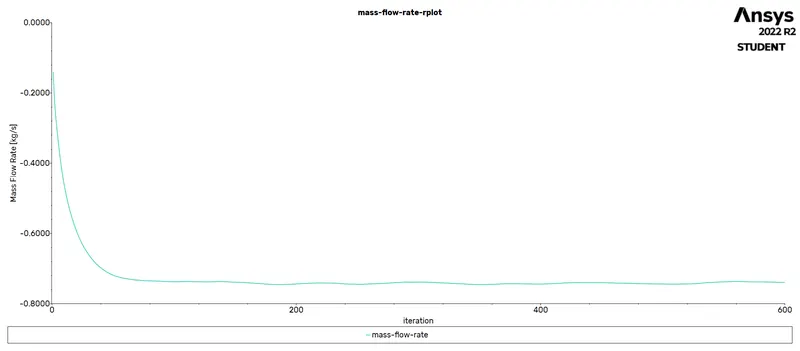
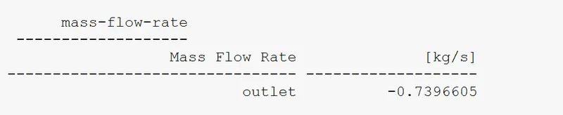
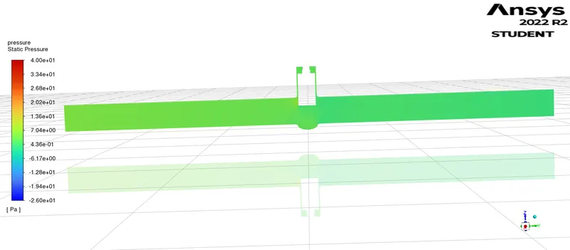
CASE - 8 , LIFT = 80 MM
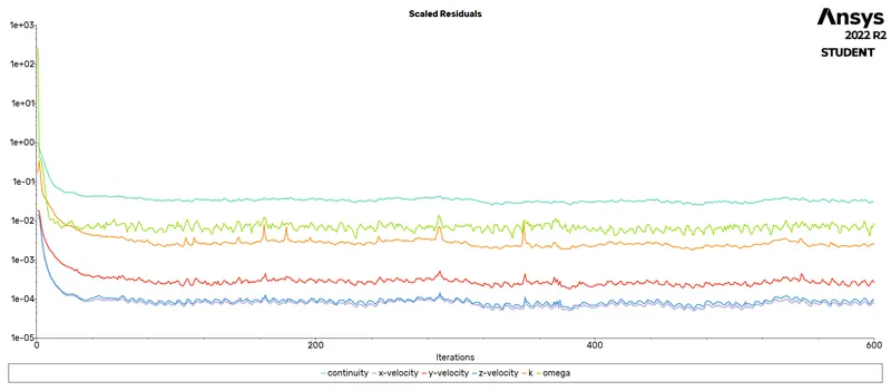
RESIDUALS
MASS FLOW RATE
VALUE OF MASS FLOW RATE
VELOCITY CONTOUR
PRESSURE CONTOUR
TABULATIONS
| LIFT | FLOW RATE (Q) | FLOW RATE (Q) | FLOW COEFFICIENT (Cv) | FLOW FACTOR (KV) |
| (In MM) | (In Kg/s) | (In GPM) | (In GPM) | In (m^3/h) |
| 10 MM | -0.14155 | 2.2435675 | 58.910 | 50.958 |
| 20 MM | -0.22678 | 3.594463 | 94.3824 | 81.6408 |
| 30 MM | -0.34 | 5.389 | 141.502 | 122.4 |
| 40 MM | -0.44073 | 6.9855705 | 183.4252 | 158.6628 |
| 50 MM | -0.52485 | 8.3188725 | 218.4346 | 188.946 |
| 60 MM | -0.59617 | 9.4492945 | 248.116 | 214.6212 |
| 70 MM | -0.67835 | 10.7518475 | 282.3190 | 244.206 |
| 80 MM | -0.73966 | 11.723611 | 307.8353 | 266.2776 |
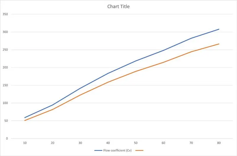
GRAPH PLOT BETWEEN Cv & Kv
CONCLUSIONS
1. As the lift of the gate disc is increased, the mass flow rate gradually rises.
2. Parametric analysis is used to examine how the flow coefficient and flow factor change as the valve is opened.
3. Parametric analysis is a time-saving choice when examining how changing a few parameters may affect a system.
4. Calculating the flow coefficient is necessary because it affects the choice of valve and the sizing of a valve.
5. The flow coefficient is also useful in calculating the system's effectiveness and the impact of pressure.