Simulating Cyclone separator with Discrete Phase Modelling
SIMULATION AND ANALYSIS OF CYCLONE SEPARATOR
l. OBJECTIVE
- Simulate the flow by varying the particle size through inlet.
- Simulate the flow by varying the velocity of particles through inlet.
- Calculate Separation efficiency and pressure drop.
ll.INTRODUCTION
1. Cyclone Separator
The cyclone separator is a cylindrical or conical container which uses a vortex for removing particulates from an air, gas or liquid stream, without the use of filters.
Air flows in a helical pattern, beginning at the top end of the cyclone and ending at the bottom end before exiting the cyclone in a straight stream through the center of the cyclone and out the top.
Large particles in the rotating stream have too much inertia to follow the tight curve of the stream. Thus, they strike the outside wall and the fall to the bottom of the cyclone where they can be removed.
In a conical system, as the roatating flow moves towards the bottom of the cyclone, the rotational radius of the stream is reduced, thus separating smaller and smalleer particles.
2. Empirical Methods used to calculate the Cyclone Separator efficiency.
2.1 Lozia And Leith Model
Lozia and leith model assumes that aparticle carried by the vortex endures the influnce of two forces:
- Centrifugal Forces
- Flow Resistances
The collection efficiency `eta_i`can be calculated as follow-
`eta_i=1/(1+(d_(pc)/d_(p))^beta)`
where,
- `betararr`An expression for slope parameter derived based on the statistical analysis of experimental data of cyclone with D= 0.25m
- `d_prarr`Particle Diameter
- `d_(pc)rarr`50% cut size given by Barth
2.2 Li and Wang Model
The Li and Wang model includes particles bounce or re-entertainment and turbulent diffusion at the cyclone wall. A two-dimensional analytical expression of particle distribution in the cyclone is obtained.
Li and Wang model was developed based on the following assumptions:
- The radial particle velocity and the radial concentration profile are not constant for uncollected particles within the cyclone.
- Boundary conditions with the cosideration of turbulent diffusion coefficient and particle bounces re- entertainment on the cyclone wall are:
`c= c_0`at `theta=0` `D_r((delc)/(delr)) = (1-alpha) omegac`at r = D/2
- The tangential velocity is related to the radius of cyclone by `muR^n`=constant.
The resultant expression of the collection efficiency for particle of any size is given as-
- `eta_i=1-exp{-lambdatheta_1}`
2.3 Kosh and Licht Model
Kosh and Licht collection theory recognized the inherently turbulent nature of cyclones and the distribution of gas residence times within the cyclone.
Kosh and Licht described motion in the entry and collection regions with the additional following assumptions:
- The tangential velocity of a particle is equal to the tangential velocity of the gas flow, i.e. there is no slip in the tangential direction between the particle and the gas.
- The tangential velocity is related to the radius of cyclone by `muR^n`=conatant.
A force balance and an equation on the particles collection yields the grade efficiency-
- `eta_i=1-exp{-2[(G_(tau_i)Q)/D^3(n+1)]^(0.5/(n+1))}`
Where,
`Grarr`A factor related to the configuration of the cyclone
`nrarr`A factor related to the vortex
`taurarr`A relaxation term
2.4. Lapple Model
Lapple model was developed based on force balance without considering the flow resistance.
Lapple assumed that a particle entering the cyclone is evenly distributed acress the inlet opening. The particle tha travels from inlet half width to the wall in the cyclone is collected with 50%efficiency. The efficiency of collection of any size of particle is given by-
- `eta_i=1/(1+(d_(pc)/d_p)^2)`
lll.PROBLEM STATEMENT
1. The fluid flowing throught the model is air.
2. The particle flowing through the model is anthracite with sizes varrying from 1`mum` , 3`mum` ,5`mum`
3. The velocity of flowing particles through the model varry from 1m/s , 3m/s , 5m/s.
lV. SPACECLAIM GEOMETRY
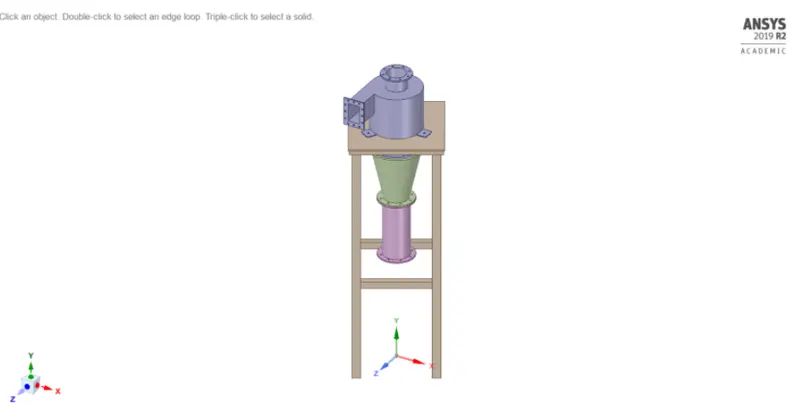
1. Solid Model
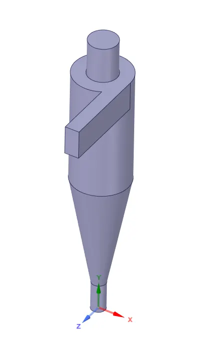
2. Fluid Volume
lV. MESH SETUP
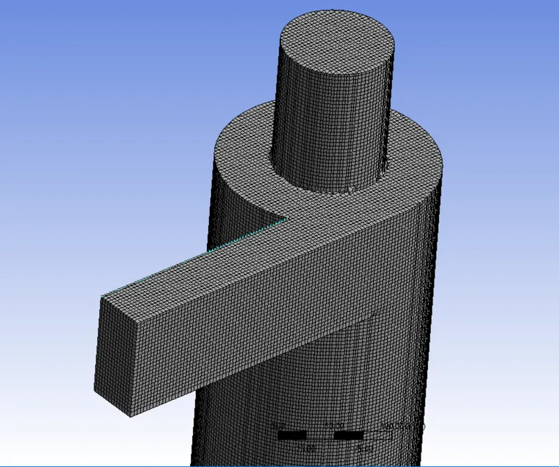
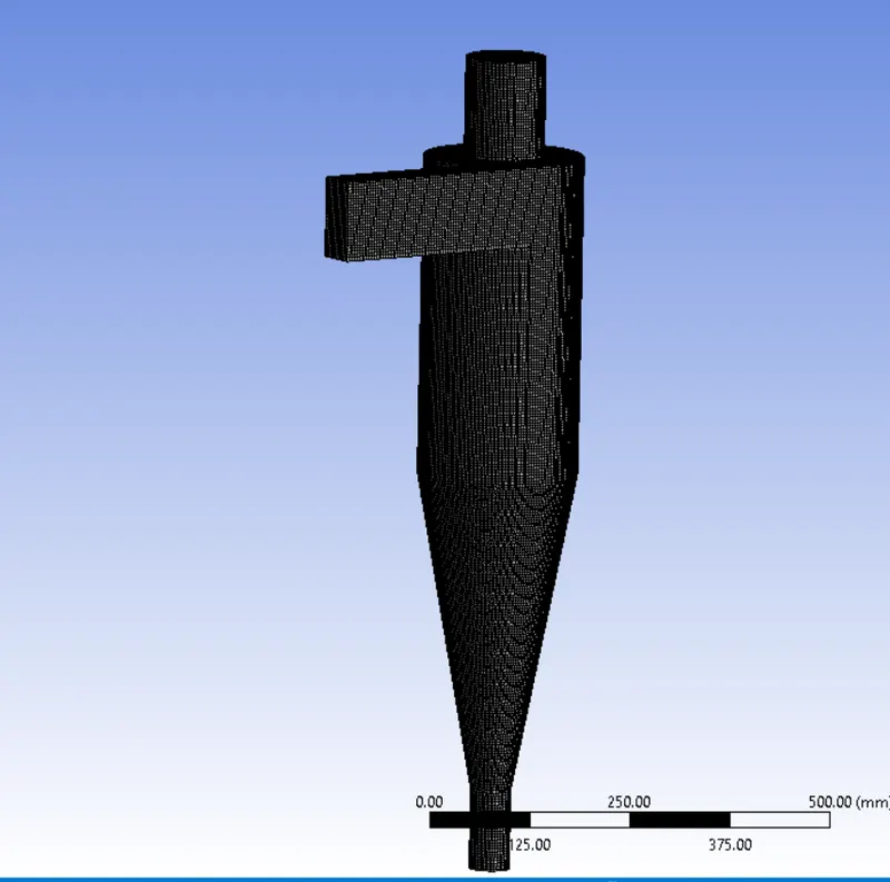
1. Method: Body Fitted Cartesian
- Geometry: Cyclone Separator Body
- Method: Cartesian
- Element size: 5 mm
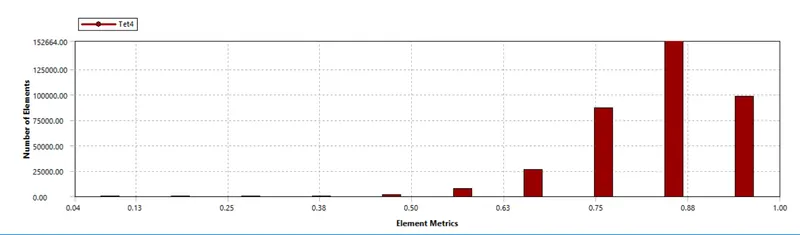
2. Number of Nodes: 456576
3. Number of Elements: 427841
5. Mesh Quality
V. BOUNDARIES
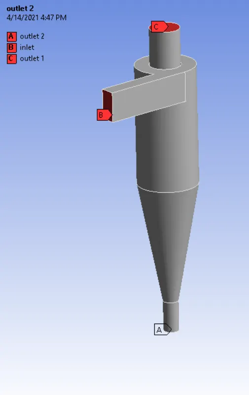
The boundaries of the geometry are generated using named selection feature of Ansys:
- Inlet
- Outlet 1
- Outlet 2
Vl. SIMULATION SETUP
1. Solver: Steady State
2. Type: Pressure Based
3. Graviational Accelaration:
- X: 0 m/`s^2`
- Y: -9.81 m/`s^2`
- Z: 0 m/`s^2`
4. Turbulance Model: k-Epsilon(RNG) with Swirl Dominated Flow
5. Cell Zone Conditions:
- Fluid: Air
6. Discrete Phase Model:
- Interaction:
Interaction with Continuous Phase
Update DPM Source Every Flow Iteration
- DPM Iteration Interval: 10
- Injection Properties:
Injection Name: injection_0
Injection Type: Surface
Release From Surfaces: Inlet
Particle Type: Inert
Material: Anthracite
Point Properties: X-Velocity = 3 m/s
Diameter: 1e-6 m
Total Flow Rate: 1e-20 kg/s
7. Boundaries:
- Inlet:
Velocity: 3 m/s
DPM Boundary Types: Reflect
- Outlet 1: Escape
- Outlet 2: Trap
8. Solution Methods: SIMPLE
- Momentum: Second order upwind
- Turbulent Kinetic Energy: Second order upwind
- Turbulent Dissipation Rate: Second order upwind
9. Initialization:
- Method: Standard Initialization from the Inlet
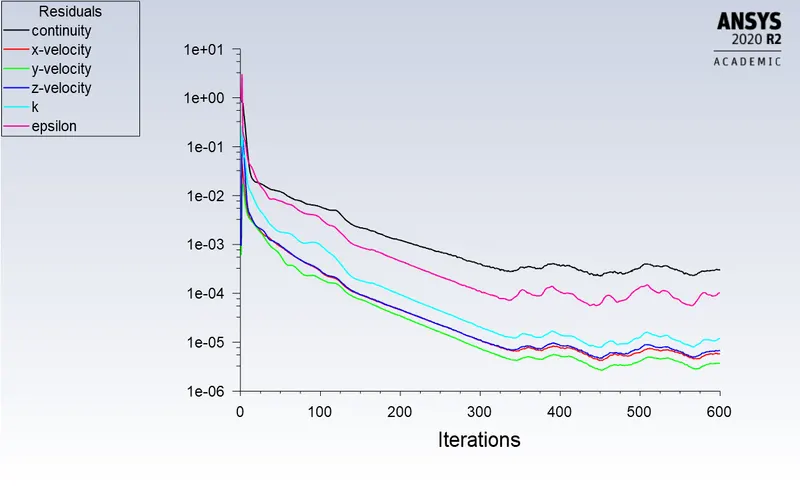
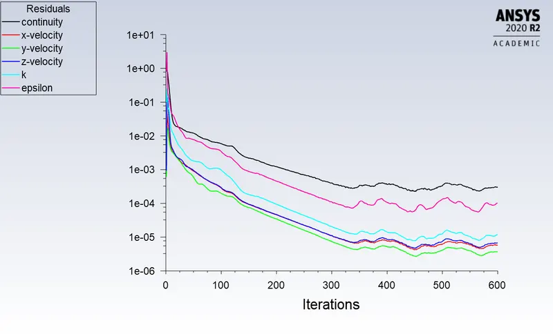
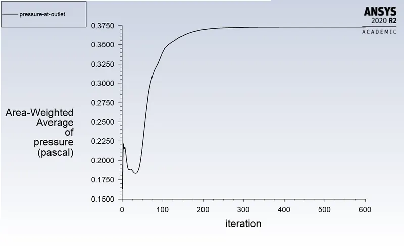
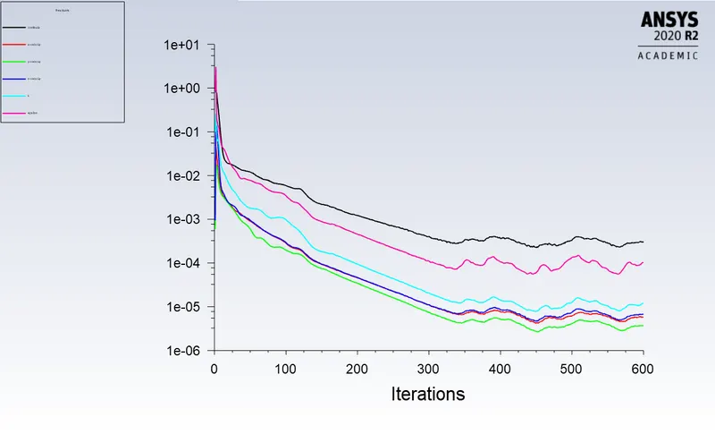
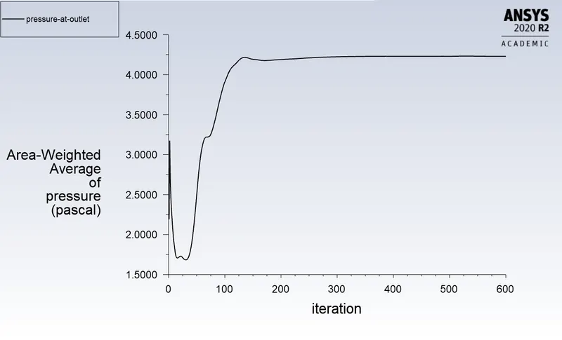
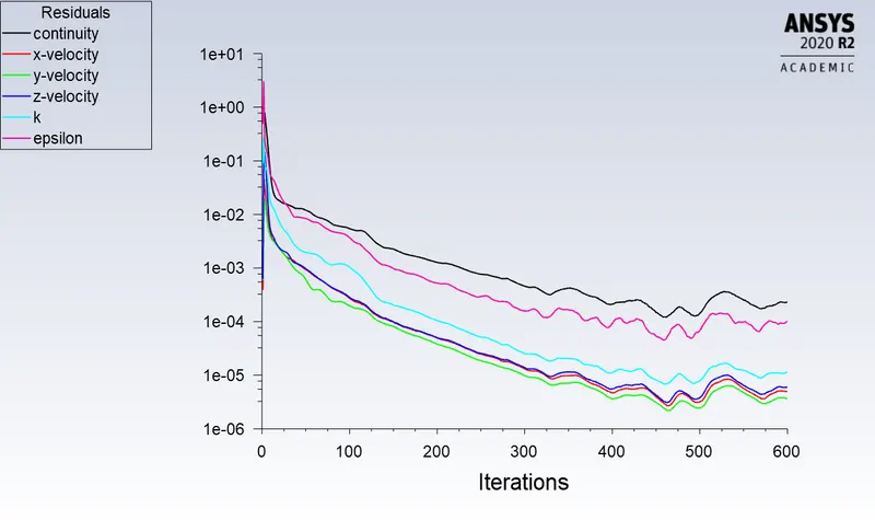
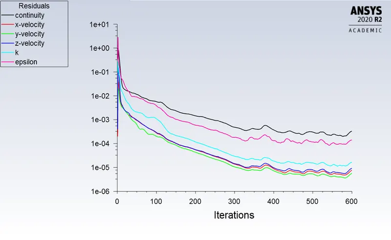
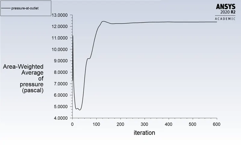
- Number of Iterations: 600
# Solution and Meshing setup remains same for all the following case.
|
DIVISION |
CASE |
X-Velocity(m/s) |
Diameter of Particle (m) |
|
CASE 1 |
A1 |
3 |
1 e-6 |
|
A2 |
3 e-6 |
||
|
A3 |
5 e-6 |
||
|
CASE 2 |
B1 |
1 |
5e-6 |
|
B2 |
2 |
||
|
B3 |
3 |
||
|
B4 |
4 |
||
|
B5 |
5 |
Vll. Case 1
A1.
A2.
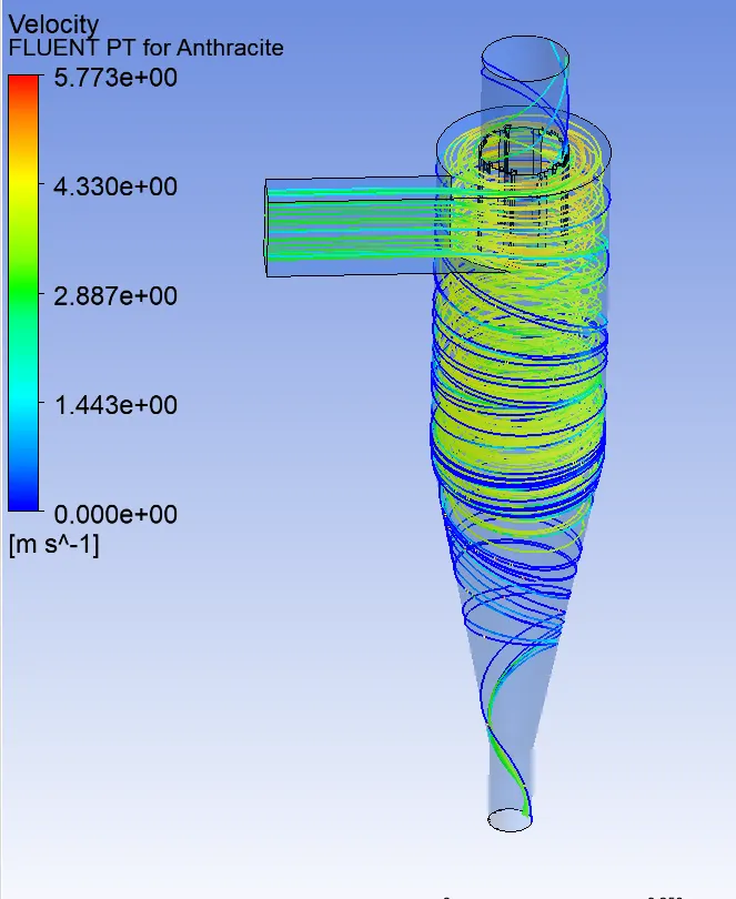
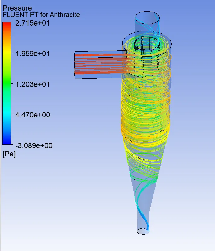
A3.
Vlll. Case 2.
B1.
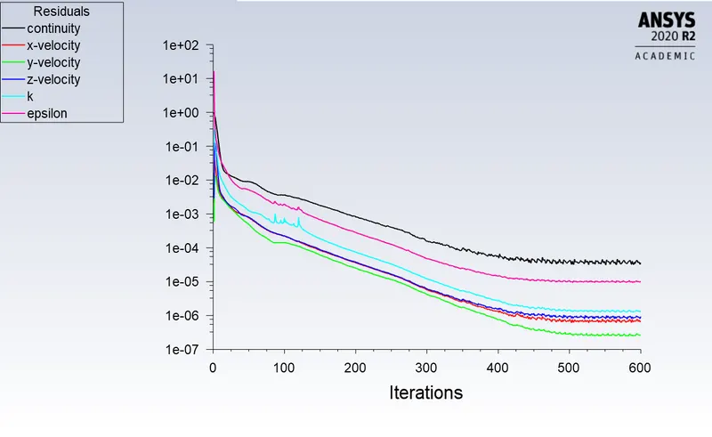
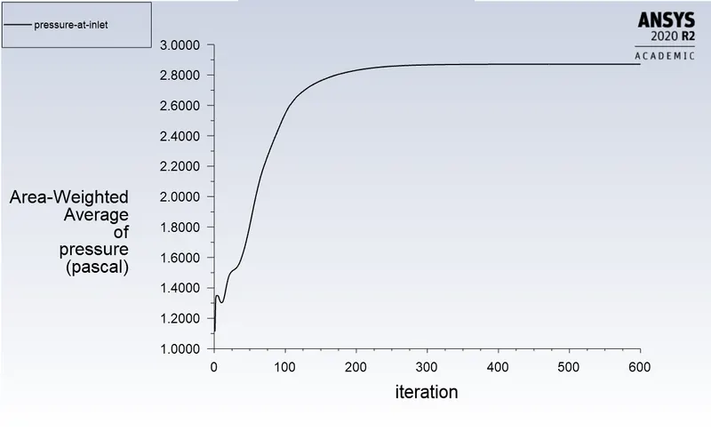
B2.
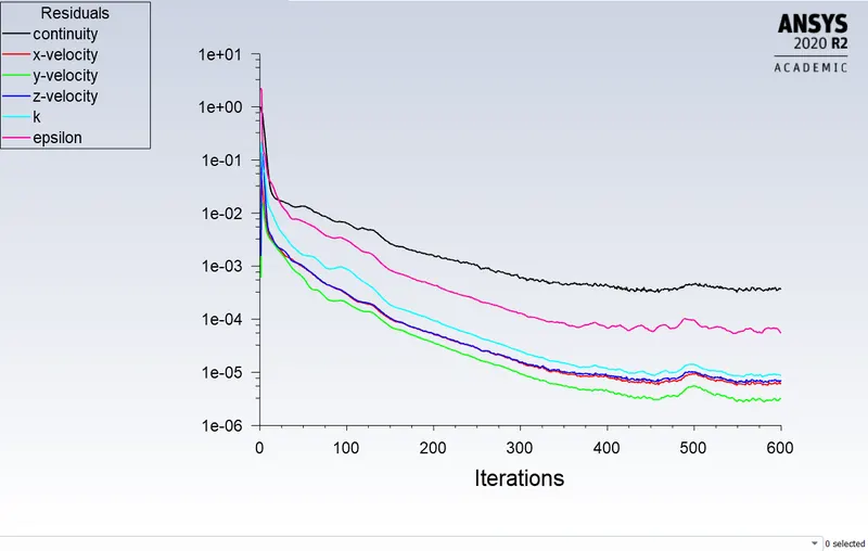
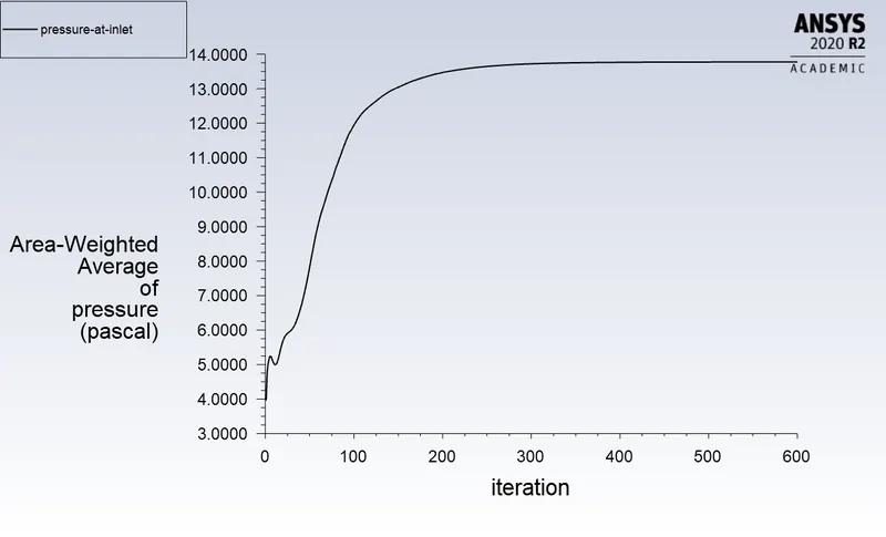
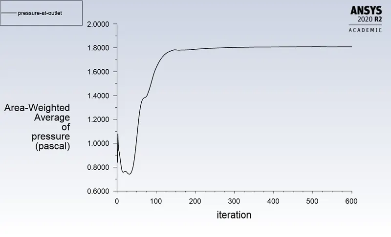
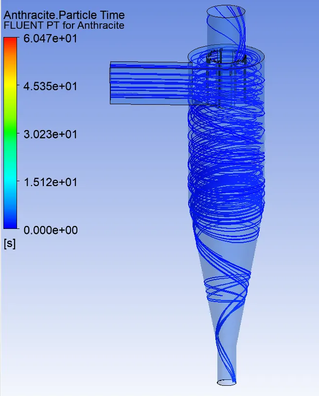
B3.
B4.
B5.
lX. OBSERVATION
CASE 1:
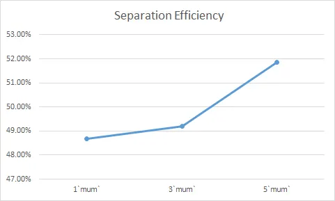
| Particle Size | Particle Tracked | Escaped | Trapped | Incomplete | Separation Efficiency |
| 1`mum` | 378 | 161 | 184 | 33 | 48.67% |
| 3`mum` | 378 | 140 | 186 | 88 | 49.20% |
| 5`mum` | 378 | 81 | 196 | 101 | 51.85% |
CASE 2:
| Velocity | Particle Tracked | Escaped | Trapped | Incomplete | Separation Efficiency (%) | Pressure Drop (N) |
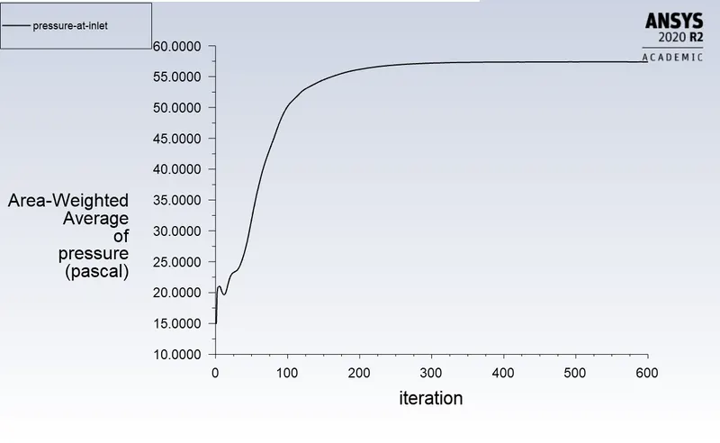
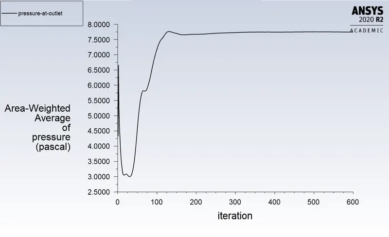
| 1 m/s | 378 | 107 | 112 | 159 | 48.46 | 2.49 |
| 2 m/s | 378 | 88 | 241 | 56 | 63.08 | 11.96 |
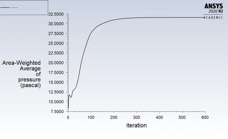
| 3 m/s | 378 | 81 | 196 | 101 | 51.7 | 27.37 |
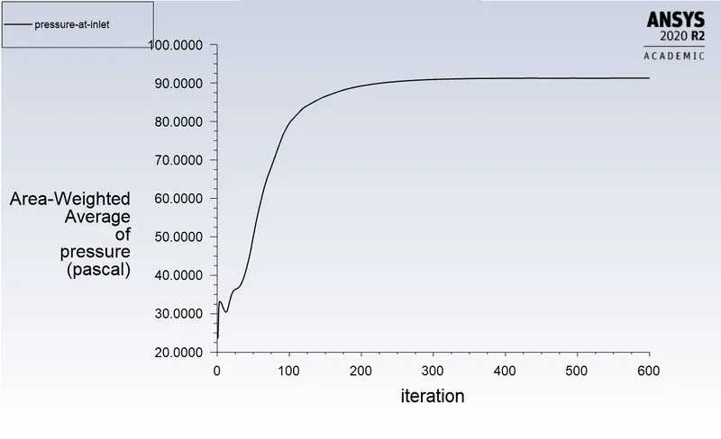
| 4 m/s | 378 | 66 | 311 | 1 | 82.64 | 49.64 |
| 5 m/s | 378 | 87 | 287 | 4 | 75.92 | 78.86 |
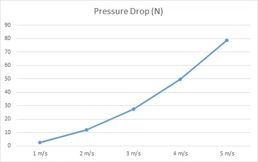
- We can see from tables that in Case 1, efficiency of separation increases with particle diameter and in Case 2, with increment of Velocity
- Also we can observe that in Case 1, Separation efficiency increases in gradual manner with increase in particle diameter.
- But in Case 2 , separation efficiency increases rapidly with increase in velocity. It is because the Pressure Drop has more impact in cyclone separator efficiency.
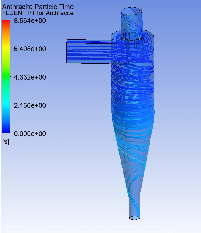
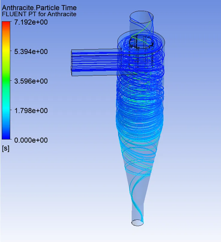
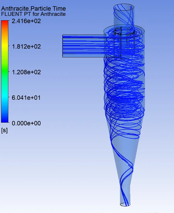
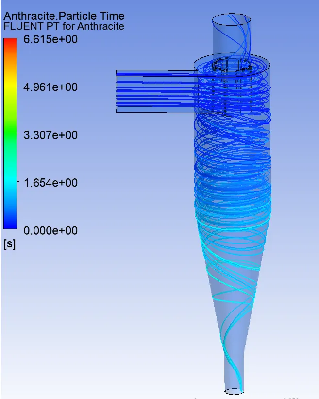
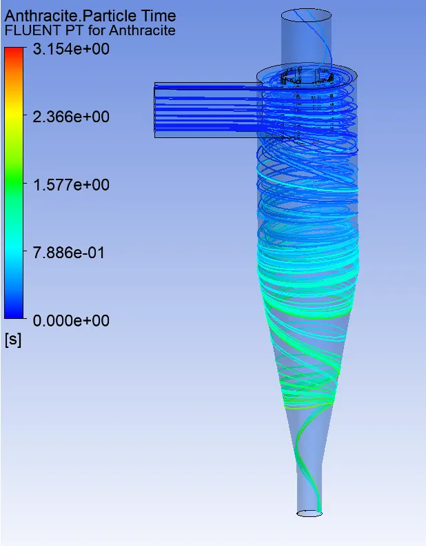
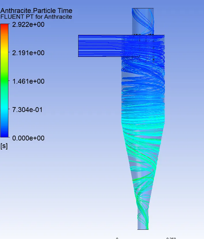
- In Case 1, particle resident time decrease with increase in particle Diameter.
- In Case 2, particle resident time decrease with increase in particle Velocity
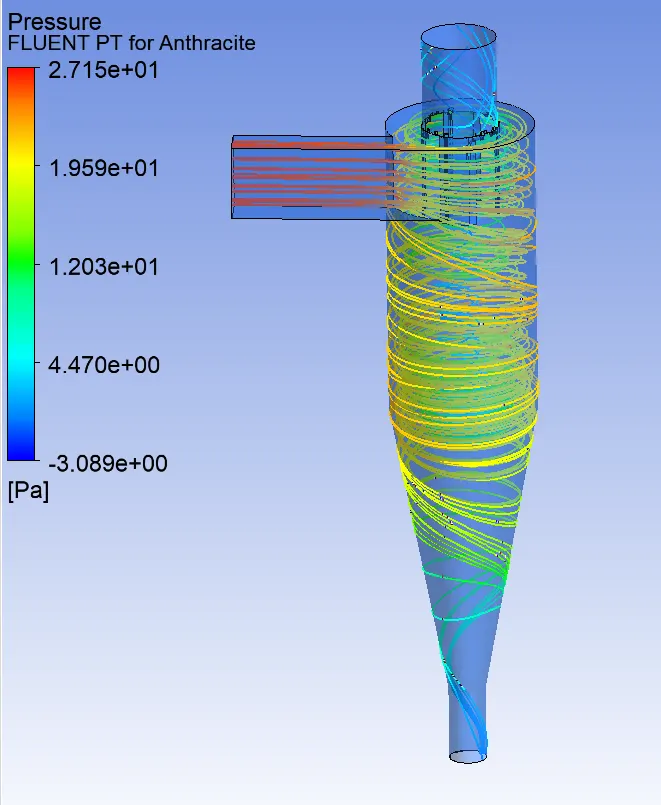
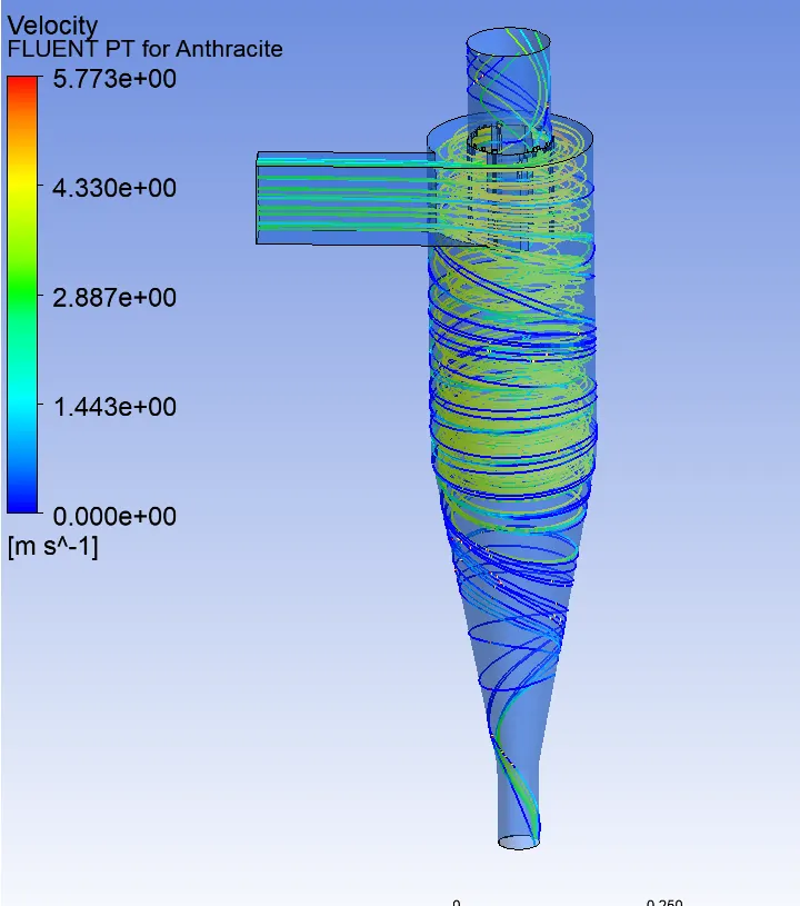
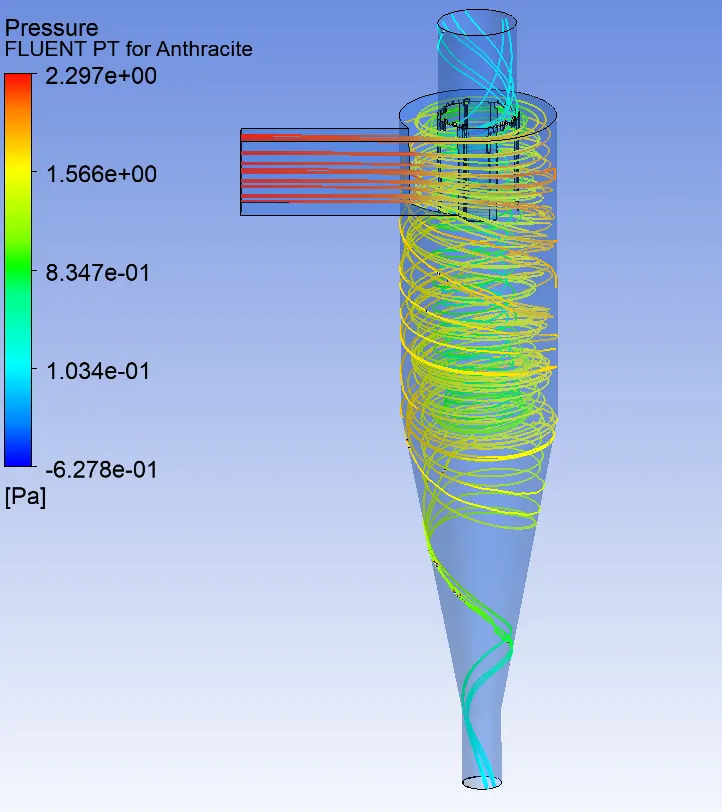
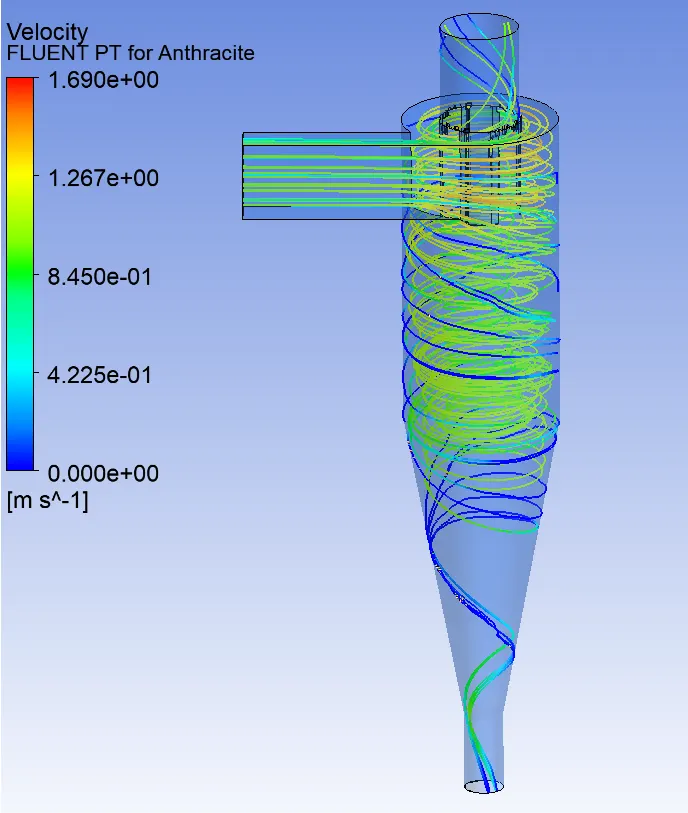
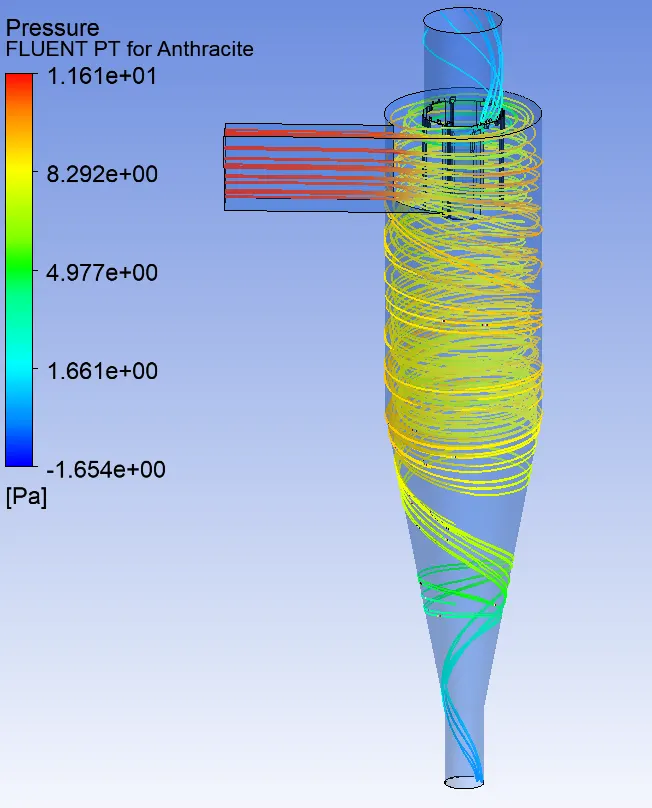
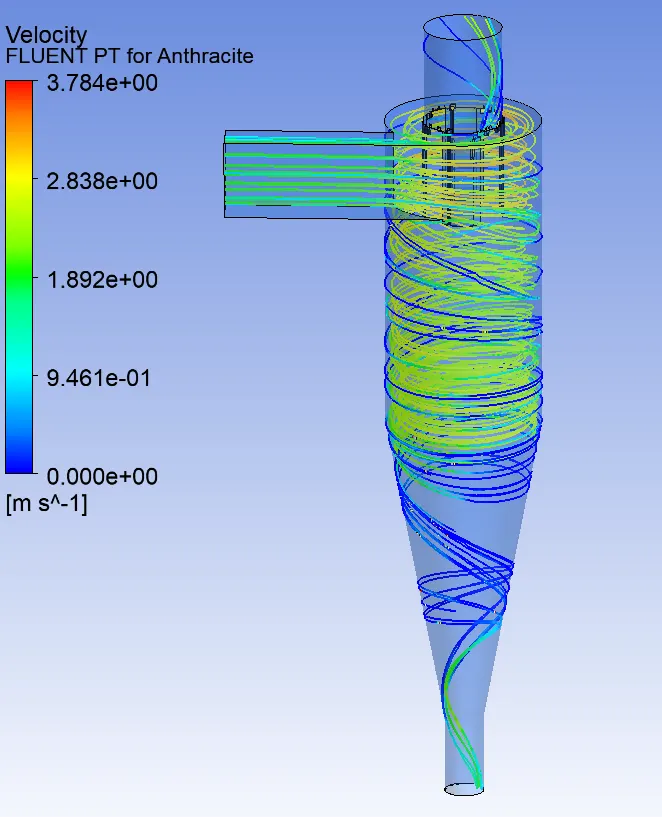
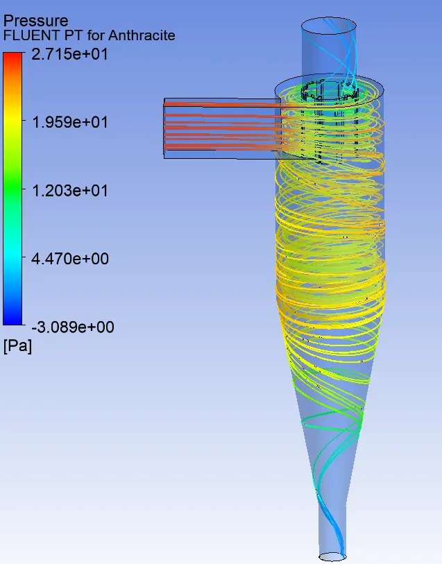
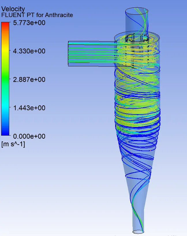
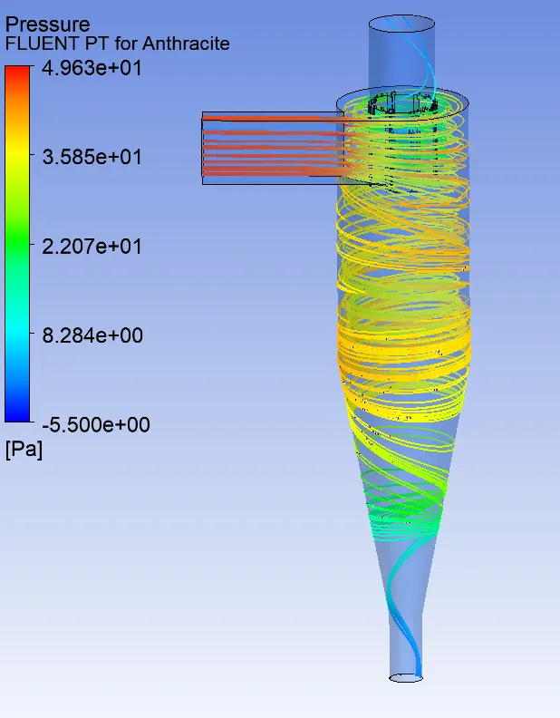
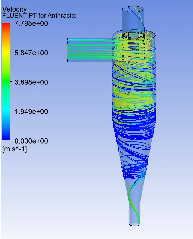
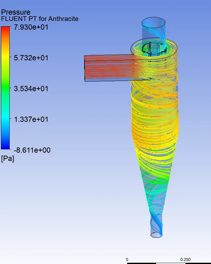
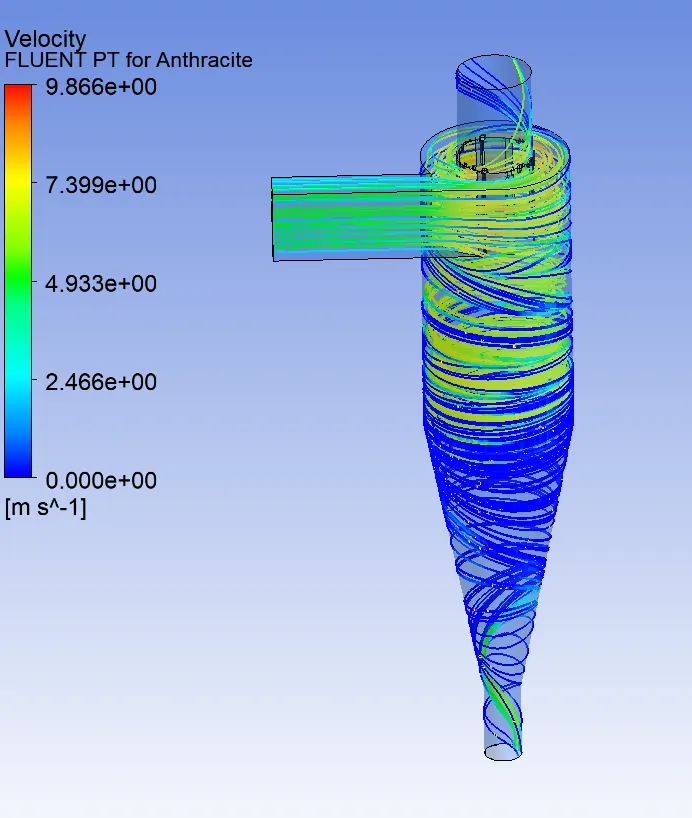
- We can see from the Pressure contour in all cases that Velocity is high at the inlet, because the Particle are being injected forcefully by the inlet.
- Also Prressure is high at the inlet and at the outlet surface of the low at the axial portion, because when particles travels in a swirl motion, they are being imparted on the outer surface of cyclone. So most of the Particles are thrown from axial to radial direction and due to that pressureat the outlet surface will always be high.
X. CONCLUSION
- We can conclude that Separation Efficiency of cyclone separator depends on both Diameter of particles and also on the velocity of the particles.
- Higher velocity is more effective for higher efficiency.
- Higher efficiency of cyclone separator has highest pressure drop.
- Higher the velocity, higher the pressure drop and heighest the efficiency.
- With increase in Diameter of Particles and velocity of particle, particle resident time decreases.
- So less resident time taken by particle results in higher efficiency of cyclone separator.