Week 8 - Simulating Cyclone separator with Discrete Phase Modelling
Simulating Cyclone separator with Discrete Phase Modelling
- Cyclone Separator:
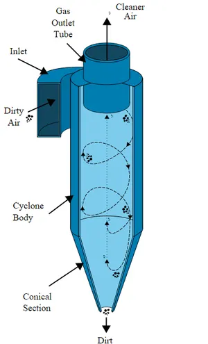
Cyclone separators are separation devices that use the principle of inertia to remove particulate matter from flue gases. Cyclone separator is one of many air pollution control devices known as pre-cleaners since they generally remove larger pieces of particulate matter. This prevents finer filtration methods from having to deal with large, more abrasive particles later. In addition, several cyclone separators can operate in parallel, and this system is known as a multi-cyclone.
It is important to note that cyclones can vary drastically in their size. The size of the cyclone depends largely on how much flue gas must be filtered; thus, larger operations tend to need larger cyclones. For example, several different models of one cyclone type can exist, and the sizes can range from a relatively small 1.2-1.5 meters tall (about 4-5 feet) to around 9 meters (30 feet)—which is about as tall as a three-story building.
Geometry setup:
Import the step file of the model into spaceclaim.
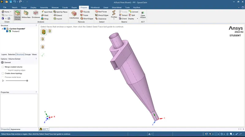
Volume extracts the model so that we can analyze the fluid flow of the cyclone separator.
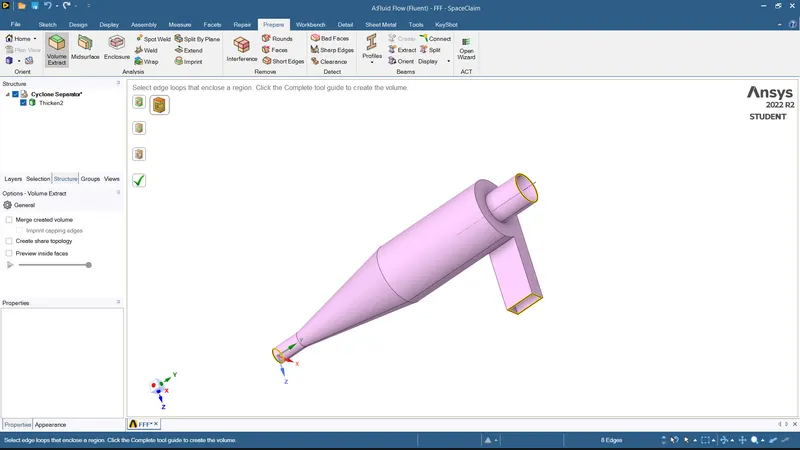
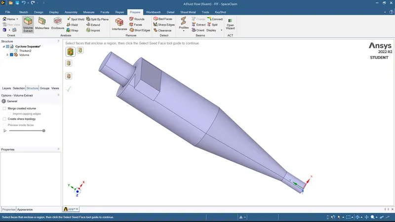
Hide the previous geometry and suppress physics since we are only interested in the fluid flow and not the external surface.
MESH:
- Element size: 8 mm
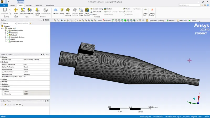
- The face selecting tool is selected. The inlets, outlet1 (top) and outlet2 (bottom) are named. The inlet is through which the particles enter the lighter impurities escape through the top, and the heavier impurities are trapped in the bottom.
Solving:
General conditions:
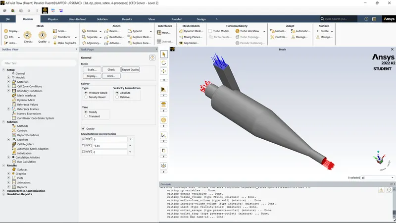
- This analysis involves the orientation of the cyclone separator. As it is in the x-y plane, the acceleration due to gravity needs to be turned on. As acceleration due to gravity acts upwards, the g value is assigned as -9.81 in the positive y axis.
- Pressure based solver is used. Steady state analysis is done, and the velocity formulation is normal to the boundary and absolute.
Physics set up:
- Turbulence modelling:
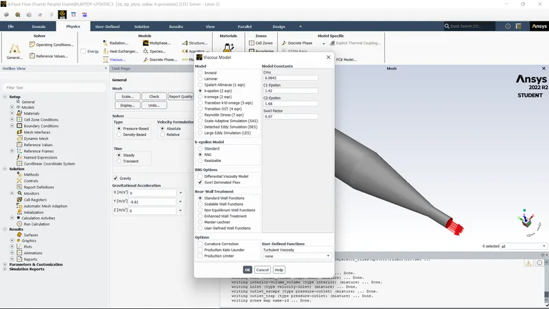
- The K-epsilon (2 equation) model with RNG and swirl dominated flow is selected. The wall malfunctions are standard wall functions.
- Since temperature is not involved, the Energy is not turned on.
DPM:
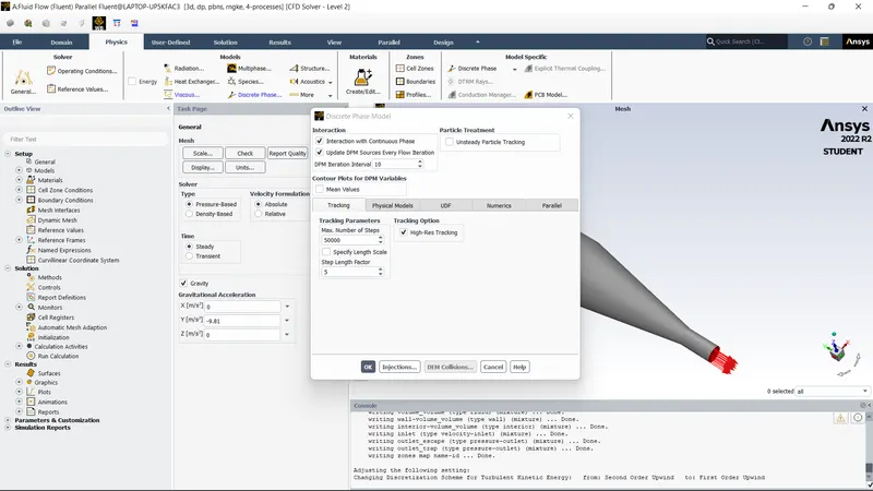
- Discrete phase modelling is opted for.
- The model is enabled for interaction with the continuous phase. DPM interval level is 10.
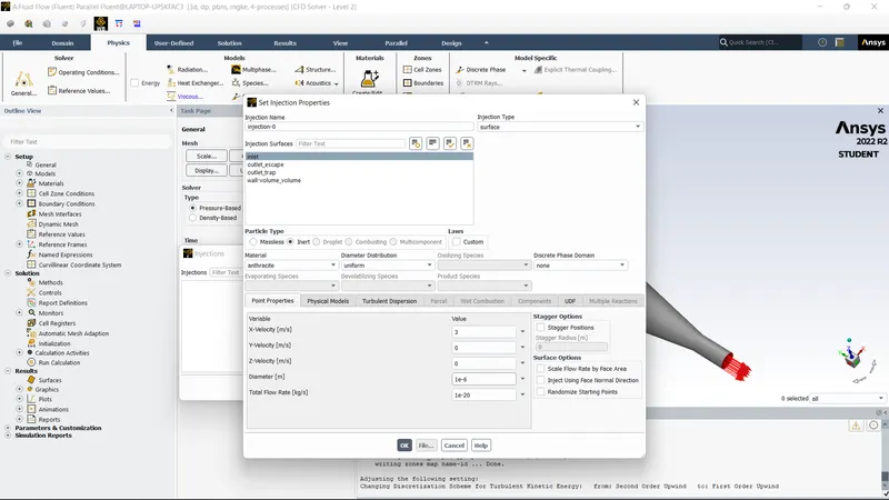
- For injection, the particle type is inert. From fluent database, anthracite is selected. It is released from the inlet, with velocity in the x-direction being 3m/s. This velocity may be manipulated further. The particle diameter chosen for the first analysis is one micrometer. The particle diameter varies from one micrometer to five micrometer to calculate the separation efficiencies.
Boundary conditions:
- The boundary conditions are provided to three named selections, inlet, outlet (1) top and outlet (2) bottom.
- For inlet, the momentum conditions are velocity is 3m/s in the x direction, being absolute and normal to the boundary. The DPM condition is reflected. This signifies that the particles are not allowed to escape or get trapped in the inlet.
- For the top outlet, the Momentum condition is basically pressure condition, The DPM condition is escape. Particles can escape from this Boundary
- The bottom outlet is also a pressure outlet, with the DPM condition being trap.
Initialization:
- Standard initialization is done with flow from inlets.
- The analysis is done for 500 iterations.
RESULT:
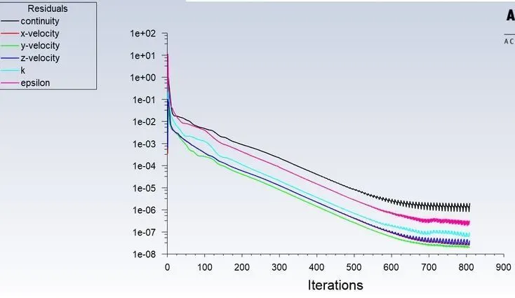
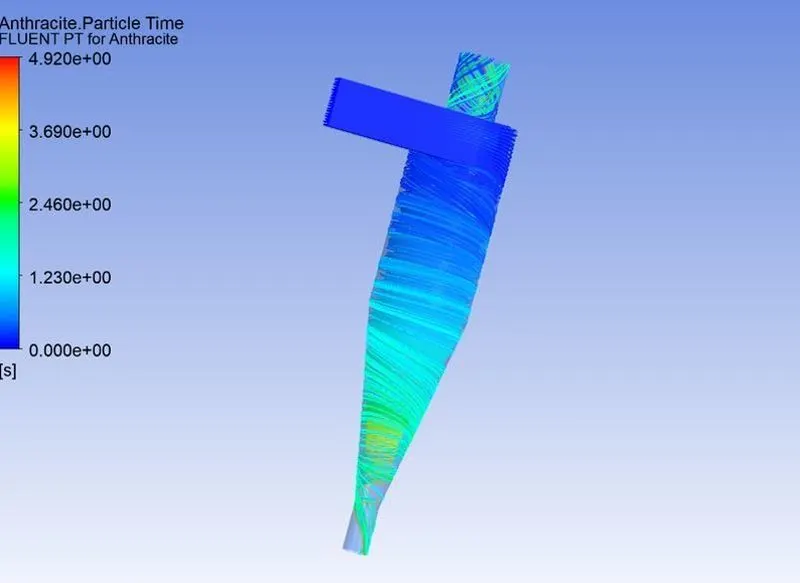
Results for the particle size of 1 micron with a velocity of 3m/s:
RESIDUAL PLOT:
Post processing:
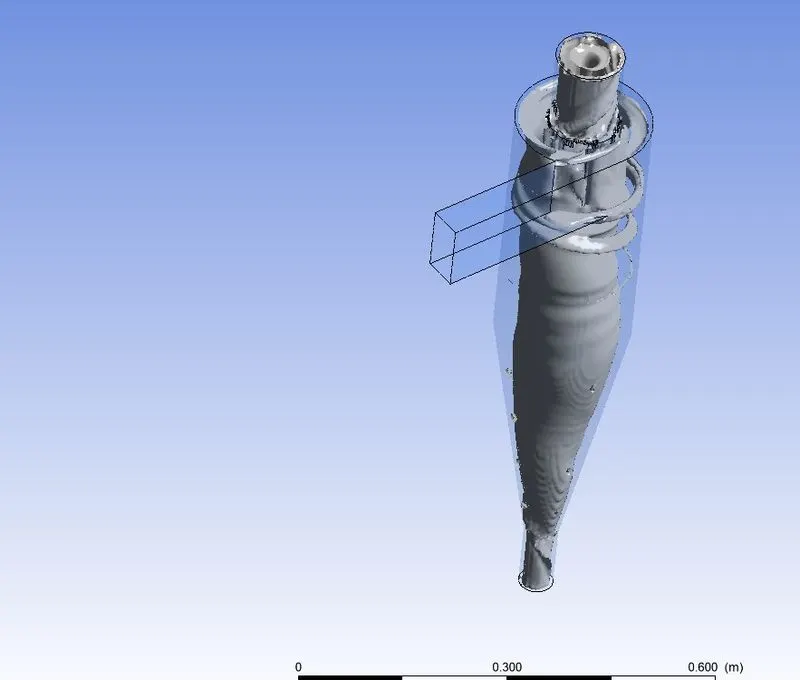
Vortex region:
Results for the particle size of 3 micron with a velocity of 3m/s:
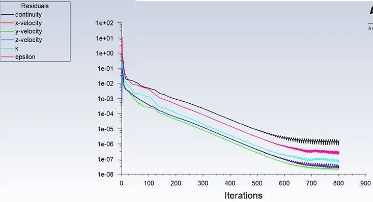
RESIDUAL PLOT:
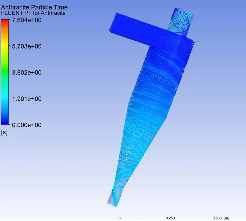
Post processing:
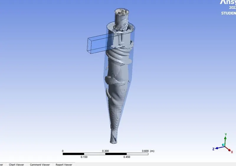
Vortex region:
Results for the particle size of 5 micron with a velocity of 3m/s:
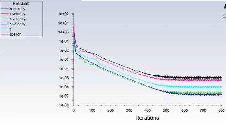
RESIDUAL PLOT:
Post processing:
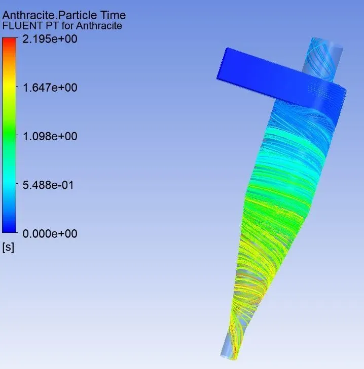
Vortex region:
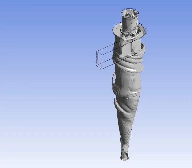
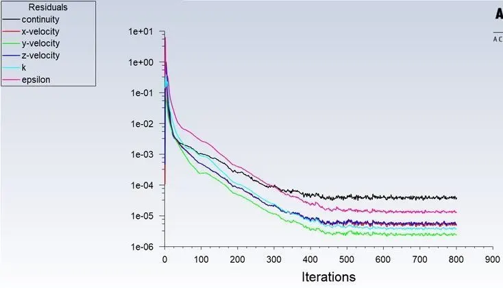
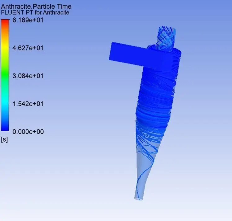
Results for the particle size of 5 micron with a velocity of 1m/s:
RESIDUAL PLOT:
Post processing:
Vortex region:
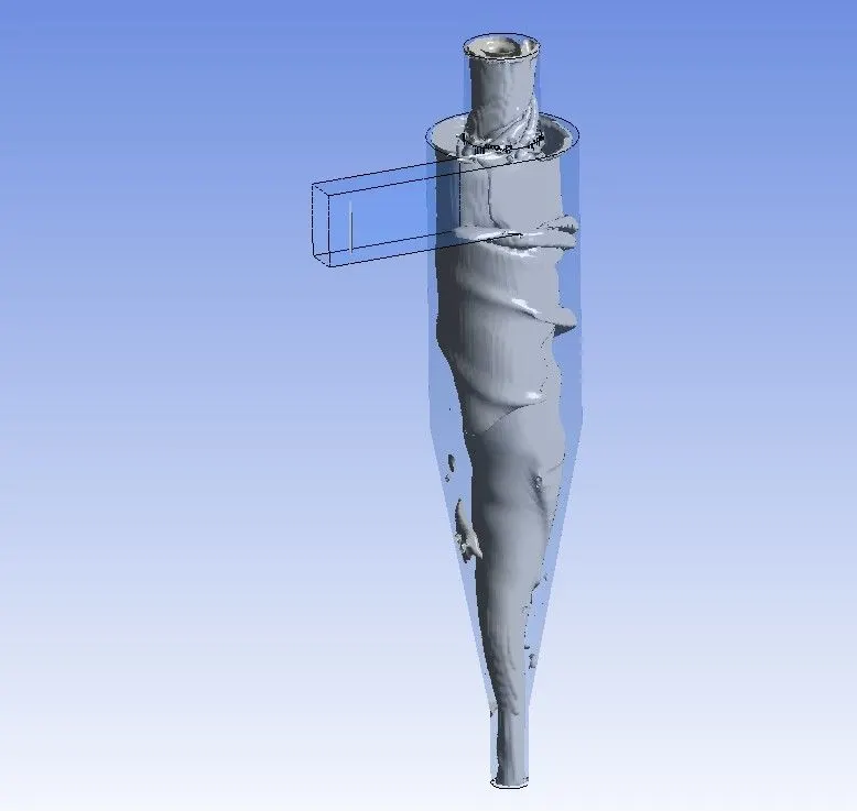
Results for the particle size of 5 micron with a velocity of 5m/s:
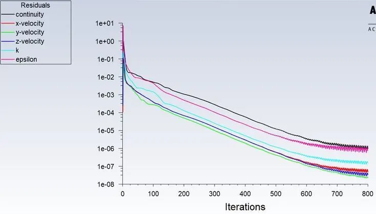
RESIDUAL PLOT:
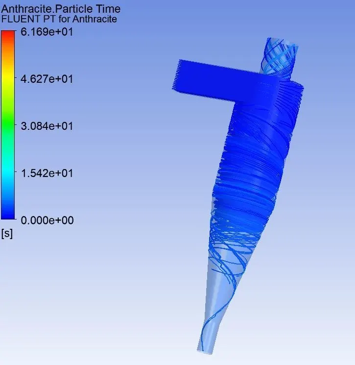
Post processing:
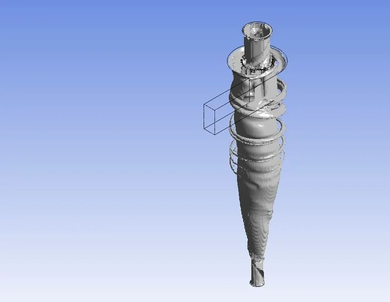
Vortex region:
Tables of all cases:
|
s.no |
Pd (particle dia) |
Pv(particle velocity) |
P tracked |
P trapped |
`Effi = (p trapped)/(p tracked)` |
pressure drops |
|
1 |
5μ |
3 m/s |
91 |
56 |
61.53 |
-0.676 |
|
2 |
3μ |
3 m/s |
91 |
60 |
65.93 |
-0.677 |
|
3 |
1μ |
3 m/s |
91 |
72 |
79.12 |
-0.388 |
|
4 |
5μ |
5 m/s |
91 |
53 |
58.24 |
-0.671 |
|
5 |
5μ |
3 m/s |
91 |
56 |
60.43 |
-0.676 |
|
6 |
5μ |
1 m/s |
91 |
75 |
82.41 |
-0.249 |
Conclusion:
As the Particle Size decreases the separating efficiency of the cyclone separator increases. As the particle size increases the Pressure drop of the cyclone separator increases. As the particle velocity increases the separating efficiency of the cyclone separator increases. As the particle velocity increases the pressure drop of the cyclone separator increases. for better results smaller element size and high mesh quality is required.
Pressure drop occurs because of the following components:
- Loss due to the expansion of gas in the cyclone chamber.
- Loss due to rotational kinetic energy.
- Loss due to wall frictional forces