Head impact on hood - LS-DYNA
G-drive link : https://drive.google.com/drive/folders/1IwB16O5a7bJgJhJMHJgDGBpx-5k5UKUY?usp=sharing
OBJECTIVE :
To simulate the pedestrian headform with the different cases such as rigidwall and meshed hood to extract the HIC(Head Injury Coefficient). The main objective is to start with the simpler head model and to do the simulation on the pedestrian headform with meshed hood is the ultimate goal. The three different cases are
- Simple head with rigidwall
- Pedestrian headform with rigidwall and
- Pedestrian headform with hood of the car.
After simulation extract the results to find out the HIC.
PROCEDURE :
- Keyword generation
- Simulation
- Output
Keyword generation :
The different keywords for the three different cases are as follows and those are the important one.
CASE 1 : Simple head with rigidwall
1. Rigidwall creation :
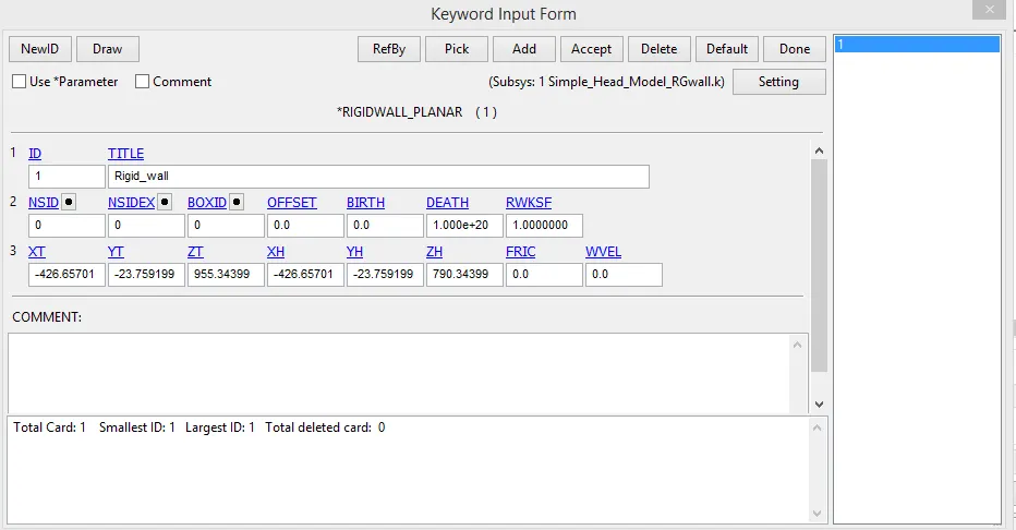
The below image shows the rigiwall created with respect to the nodes of the simple head. The rigidwall is planar and created by two nodes selection in simple head and translated to some magnitude for the specific gap between head and wall.
2. Velocity to the nodes of the head :
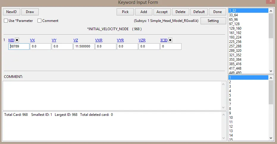
The velocity of 40kmph is applied to all the nodes of the head in particular axis so that it will hit rigidwall and create impacts on the head. Here the velocity of the nodes is in direction of z-axis(+ve).
Simulation :
Output :
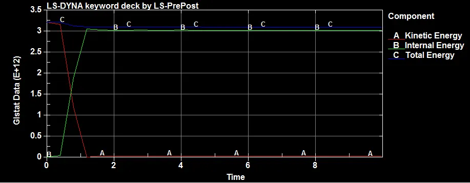
The above graph shows the energy content of the above system. For plotting the three different kinds of energy are selected.
- The total energy remains almost constant for the entire time period of simulation.
- The internal energy initially lower and it enormously increased.
- The kinetic energy is initially higher and it decreased. These two energies(internal and kinetic energies) are varying oppositely. This is because all the kinetic energy of head(due to 40kmph) stored as internal energy after hitting since there are no motion of head after it hits the wall.
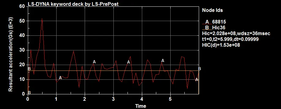
The above graph shows the resultant acceleration on the particular wall hitting node. The frequency is fluctuating more since it is a shell component it deformed much. If this head is solid, then the resultant acceleration of the node will be different or fluctuates less than this. The HIC value is almost from intial to end of the simualtion. It is because that the entire problem is done for only 5msec but the HIC is choosed for the total of 36msec. It can be varied based user desire.
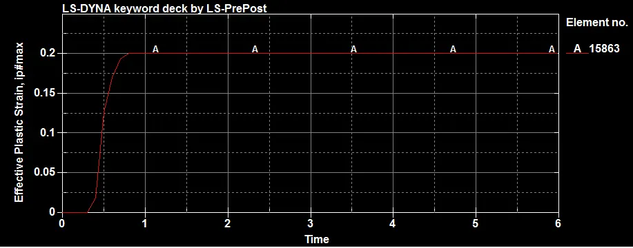
The above image depicts the result of effective plastic strain vs time. The element 15863 is choosed for the strain result. Since this is a shell element the element deformation is permanent i,e the plastic region of the curve is constant. The linear portion of the curve is completed within 0.5 msec. The constant portion of non-linear section of the curve is due to contact dis-connected between wall and head.
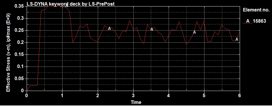
The above graph shows the result of effective stress of the element choosed. The curve is too noisy and it can be filtered using filter option but it will result in approximate result. The more noisy curve is only because the head is shell element.
CASE 2 : Pedestrian headform with rigidwall
1. Define transformation card
In this card the tranformation of the including file to be added and TRANSID is assigned. Here the Pedestrian headform is rotated with 45degree in respect to y-axis. By this define card the model will be located in the included file based on the values assigned in the *DEFINE_TRANSFORMATION card. There are different OPTION in this card. If ROTATE is used the headform will be rotated with 45degree. And if needed to mirror the model, translate the model etc. the appropriate OPTION should be used and it will be aligned.
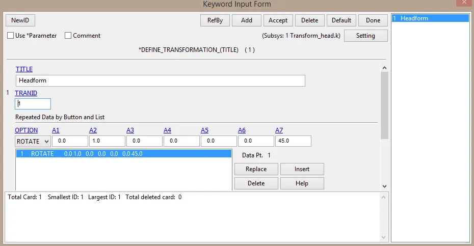
2. Include transformation card
In this the required modell will be input into the .key file by browsing the model in the system. Here the PEDESTRIAN_HEADFORM file is included through this card. Thus the headform model will be included and will aligned to the rgwall based on the values on *DEFINE_TRANFORMATION card.
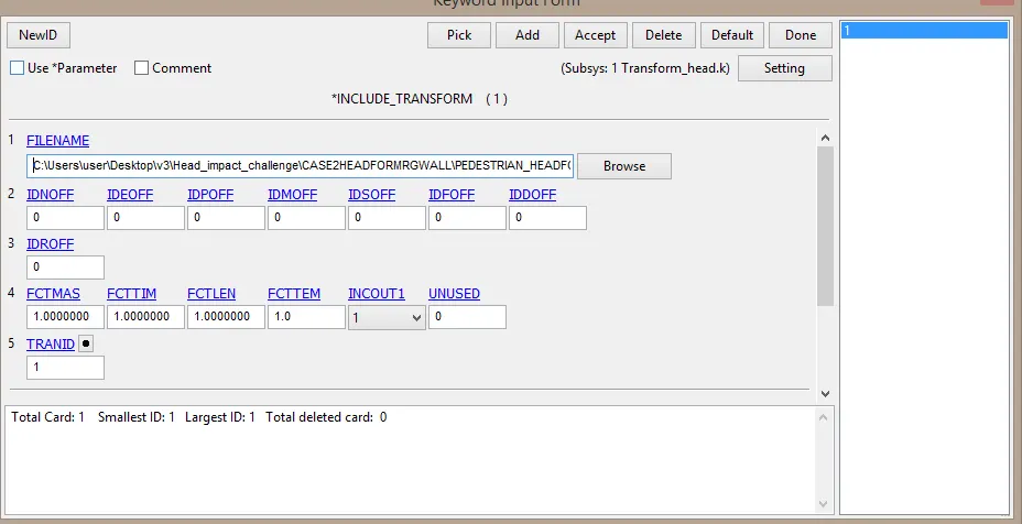
The scale of the unit can be varied using FCTMAS. If the unit in headform is gram, then the magnitude of 1000 will be entered in FCTMAS to convert the unit of 1gram to 1 kilogram.
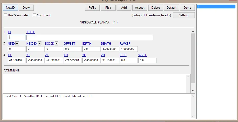
3. Rigidwall creation
The rigidwall is created with respect to the nodes of PEDESTRIAN_HEADFORM.
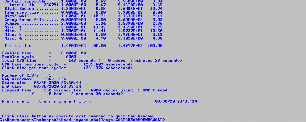
Simulation :
Output :
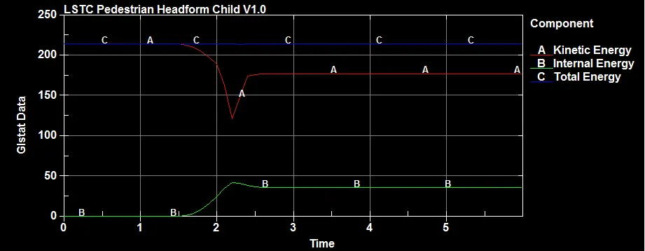
The graph clearly shows the energy content of the system. The kinetic energy and internal energy not crosses like in the case-1 since the headform is more stiffer than simple head and it is the absolute head material for the safety test. The total energy remains constant.
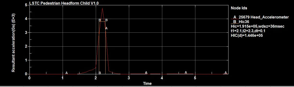
The HIC value is enormously high, since the Headform is made to hit the rigid wall at a speed of 40kmph. The HIC value is HIC(d)=1.446e+05. This value is nearly 14 times greater than the ultimate value of HIC defined by the safety department. But this is for the simulation purpose only.
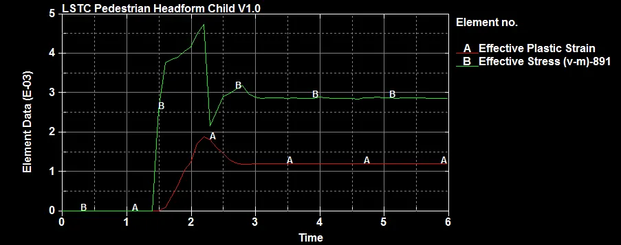
The above graph shows the relation between time and strain and stress. The strain created in the headform is not proportional to the stress created.
CASE 3 : Pedestrian headform and meshed hood
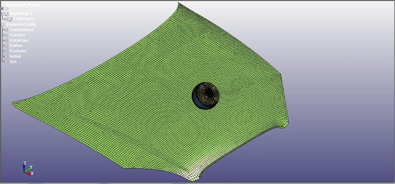
The pedestrian headform is directly included into the hood model with respect to the origin of the hood.
1. Define transformation :
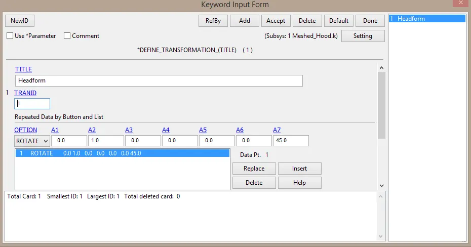
In this card the tranformation of the including file to be added and TRANSID is assigned. Here the Pedestrian headform is rotated with 45degree in respect to y-axis. By this define card the model will be located in the included file based on the values assigned in the *DEFINE_TRANSFORMATION card. There are different OPTION in this card. If ROTATE is used the headform will be rotated with 45degree. And if needed to mirror the model, translate the model etc. the appropriate OPTION should be used and it will be aligned.
2. Include transformation :
In this the required modell will be input into the .key file by browsing the model in the system. Here the PEDESTRIAN_HEADFORM file is included through this card. Thus the headform model will be included and will aligned to the hood of the car based on the values on *DEFINE_TRANFORMATION card.
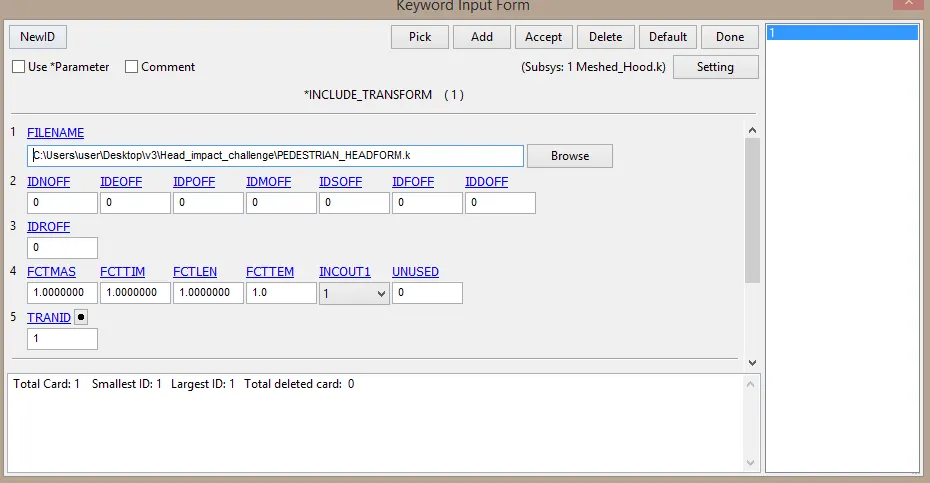
SIMULATION :
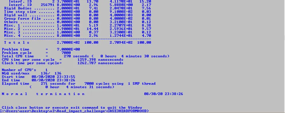
OUTPUT :
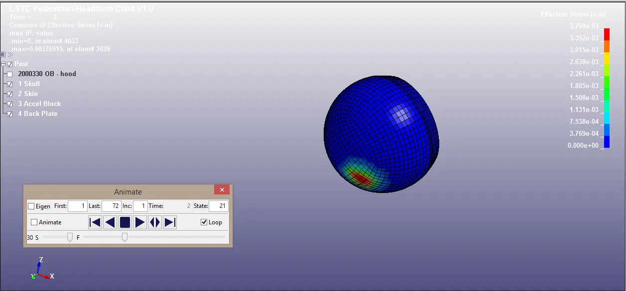
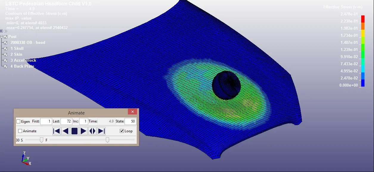
The above two images shows the effective stress in the headform. Hood is disabled to view the stress in the headform in first image. The second image shows the stresses in the hood. The Hood is deformed more since the thickness assigned to the hood is 2mm.
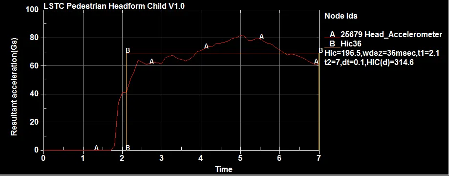
The HIC and resultant acceleration are in the above image. HIC(d)=314.6 which is lower when compared to the case-2. And when it compared with the standard for HIC, it is clear that even 1year child injury rate is not yet reached. The HIC for 1 year old child is 390 as per the NHTSA. The value from the above graph is 314.6. So it is safe to have this value. It may cause injury but very lower level injury only. This all are only by the minimum thickness of hood. If it increases then the HIC value will increase.
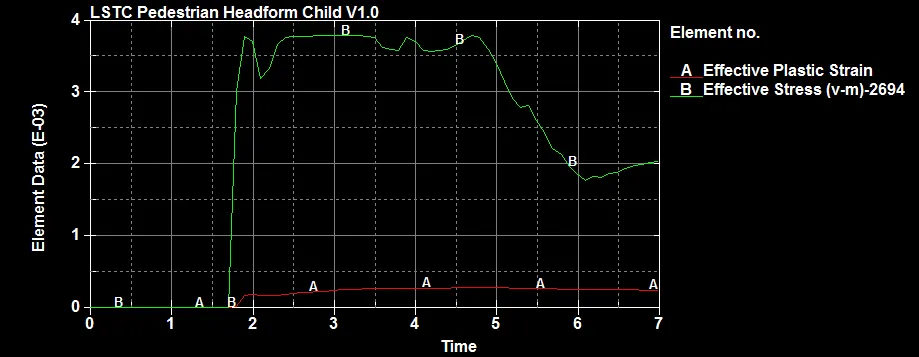
It is clear from the graph that the strain is much smaller when compared with stress.
CONCLUSION :
Thus the headform with meshed hood is simulated and the results are extracted and compared with each other. It cleary shows that the HIC value depends on the thickness of the hood and velocity by which the head will hit the hood. This is why most of the hood of the car are thin to minimise the injury for the trespasser.
From this project the belows are the learnings.
- How to inlude the file to the parent file?(having connections between all the files).
- How to define the transformation for the included file?
- What are the range for safety test like HIC values?
- Seo Offpagesamazing - creative thinks media.