Roll over crash simulation - Crashworthiness using Hyper Mesh and Radioss
OBJECTIVE:
To simulate the roof crash of the car using impactor over the left side of the car. The impactor is in the FMVSS(Federal Motor Vehicle Safety Standards) standard. Impactor is like rectangular slab comprising four components with rigid bodies and spring to move impactor towards roof of the car.
Roof crash is simulated for the rollover accident cases. When the car rolls over the track it mostly creates impact on the roof of the car. In order to simply the simulation for rollover cases, FMVSS used to create the impactor which is a rigidbody and creates deformation like the car crash with tract of the car. In left hand side of the car for stiffness purposes, rigidbodies are used to connect all the free end parts. If rigidbodies are not used, the free end parts tend to move all over the GUI. To prevent this rigidbodies are used.
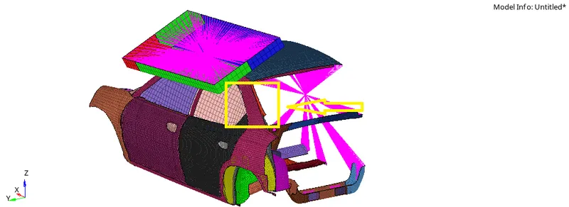
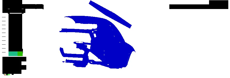
Not all parts of the real car are used for the simulation. Available parts in the below image are sufficient for the simulation.
PROCEDURE :
Import:
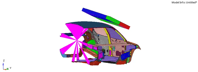
In roof crash, car BIW and Impactor are different .rad files. Both the files are imported successively to show have in a single .rad file. Once the impactor is imported in car BIW .rad file, some of the translation and rotations has been made for the proper location of impactor above BIW. The followings are the things made for the proper location of impactor.
• A 180° rotation about the global z-axis with the point opposite to C as base point
• A 5° rotation about the axis through axis AB
• A 25° rotation about the axis through axis AC
• A translation to put point A at global ( -3500.00, 584.822, 1343.06)
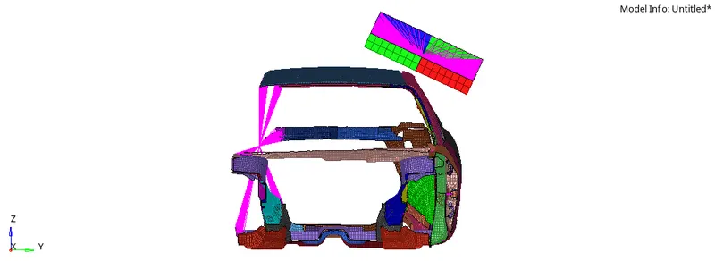
The above image depicts the proper location of impactor over BIW.
Interfaces:
Here there are two types of interfaces required. One is for the contact between the components of car parts. Another one to have contact between car and impactor. When the impactor hits the car, all the components of car would have contact with each other.
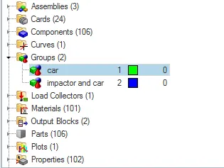
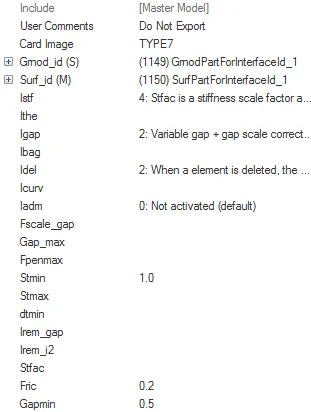
Above image clearly shows the two number of contacts. Below image shows contact between different components of the car. For Grnod_id, all the nodes of the neon BIW are selected. And for Surf_id, all the components of the neon BIW are selected.
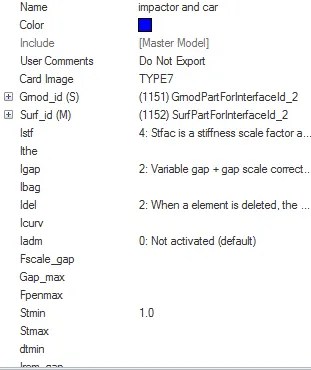
Below image shows the contact between impactor and BIW of the car. For Grnod_id, slave nodes(nodes belong to BIW of the car) are selected. For Surf_id, impactor components and rigid bodies are selected. Surf_id will be the master segment and Grnod_id will be the slave segment.
Boundary conditions:
Boundary conditions are the ones to define the constraints of the components of the system. Here the neon BIW will be the stationary component which needs not to move in any direction. Only boundary conditions for BIW is to undergo deformstion when the impactor hits it. So that in all translational and rotational directions, boundary conditions are set to be . This will tend the BIW to move in any directions only if the impactor hits it.
Impactor boundary conditions:
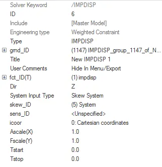
Impactor is having different BC's when compared with BIW. Impactor needs to move towards BIW. For that it needs to define the angular movement as well as the translational movement in required direction. Skew has been introduced for the better definition. Skew can be created at anywhere between the components by user definition. This will eliminates any one the rotational and translational movement, if the component is required to move in inclined manner. Here the skew has been created for the middle master node of the rigidbodies. From the skew axis, the displacement is provided in the direction of Z-axis.
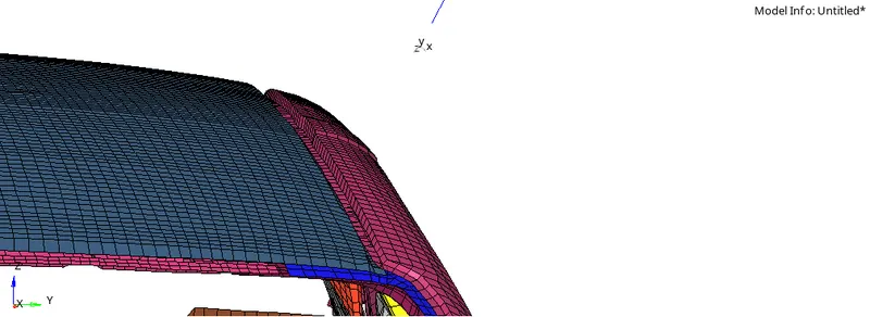
In BIW, some of the gaps are not connected with rigid bodies. This will create some of the collapse in simulation. Those gaps are filled with rigidbodies. One end of the spring is connected with rigid bodies master node and another end is free end. Free end is constrained in all directions. Spring stiffness also reduced in the favor of allowing impactor to move freely.
Imposed displacement
Imposed displacement is defined as the displcement for the body in particular direction without considering the opposing forces. The displacement will remain constant even if the body is pushed out by opposing body. For impactor imposed displacement is applied so that even it hits roof of the car it will move with constant displacement. This reflects the concept when the car roll over track. The track will remain in same position or will deform the car without considering the opposing force created by car BIW.
Control cards:
Control cards generate the results or output for the simulation if the required inputs are given. Below are some of the required results applied as input.
• /ANALY card - Describes the analysis flags. Parallel arithmetic option is turned ON which makes the simulation to run more than one bit or digit of a number at a same time.
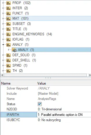
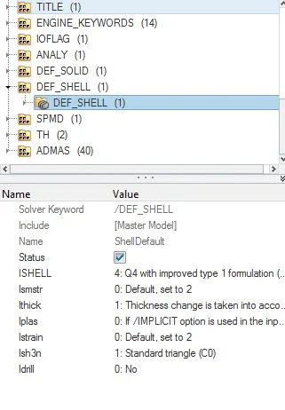
• /DEF_SHELL card - To define the formulations for shell elements. Thicknees of the shell components are taken into consideration.
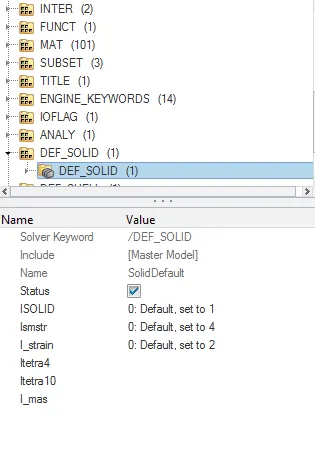
• /DEF_SOLID card - Since the solid element is used, formulations for the elements for solid are defined here. In roof crash only one solid body is available. The component is OB-DOOR-FT-LOCK-L.
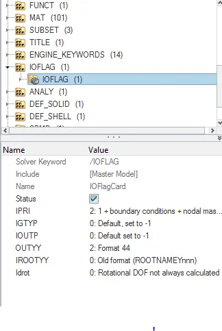
• /IOFLAG card - Describes the input and output flags.
• /SPMD card - SPMD card describes Single program multiple data which is in the need of achieving parallelism. DOMDEC is set to default value 3. If the problem is implicit in nature then it is advised to change to 5.
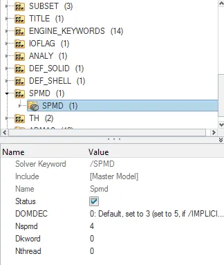
• /TITLE card - Title card gives the title of the simulation.
Engine file:
Engine files are meant to run the simulation with desired characteristics from user. Some of the characteristics are print timehistory for output, animation files to write at which time, timestep to evaluate the results etc.
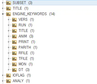
Time history is printed at every 0.0001ms. Total runtime for the roof crash is 200ms. Animation file is requested at every 0.005ms.
SIMULATION :
OUTPUT :
Kinetic and Internal energy:
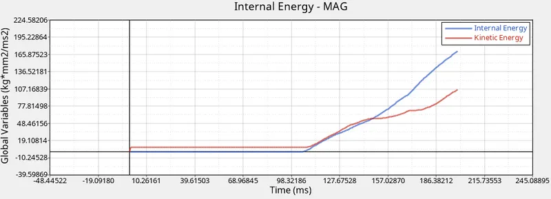
For half of the simulation both kinetic and internal energy remains constant until it made contact with BIW of the car. After the contact has been developed between impactor and car both the kinetic and internal energy increases linearly.
Contact energy :
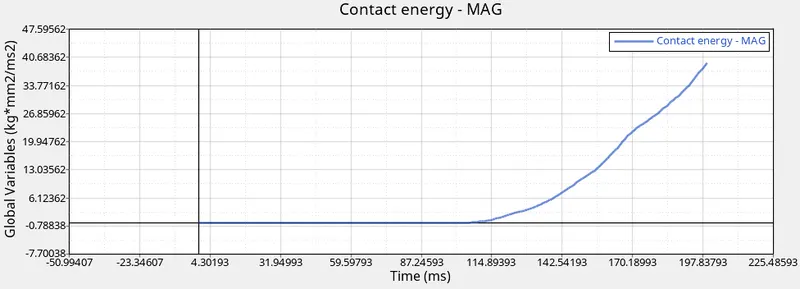
Contact energy is linearly increasing after the contact between impactor and car developed. The maximum contact energy is 39kg*mm^2/ms^2.
Mass :
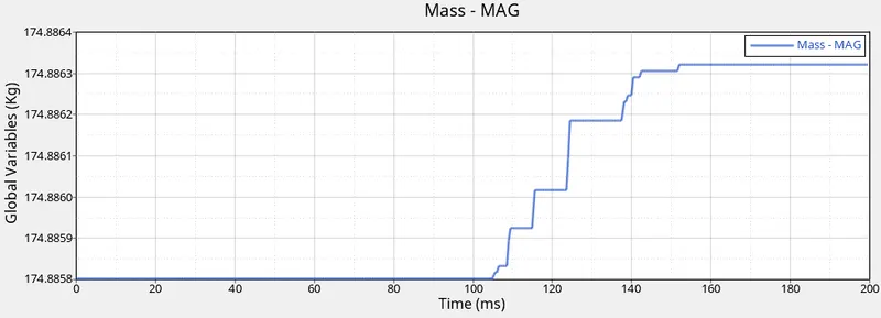
Mass is getting added to the system after impactor hitting the car roof. As the time increases, mass addition is also increasing and after 150ms mass addition remains constant till the end.
Timestep :
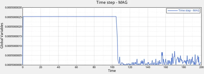
Like all other above energies, timestep variation after hitting fluctuates in both up and down with more noises throughout the length of the curve.
Total energy :
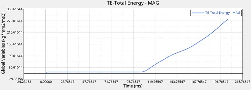
The maximum total energy for the roof crash model is nearly 280kg*mm2/ms2.
Resultant force of interface of rigid and car :
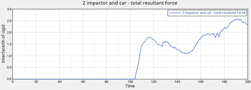
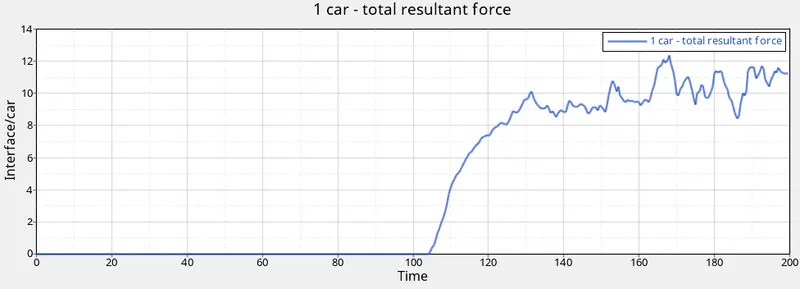
The force generated in the interface case of car and impactor is much lesser than the car. The maximum force generated on the car is 12.2N. But in the rigid interface the maximum force generated is 2.6N.
CONCLUSION :
Thus the roof crash for the car is simulated successfully and the results are defined in detail above.
From the simulation it is recommended to increase the strength of the component in the below image. This could be done by changing the material of the mentioned component. More deformation is occuring in this component which create more injury to the passenger.