Bird strike with rotor of an airplane - LS-DYNA
OBJECTIVE :
The main objective of this project is to rotate the blades in the airplane and to hit the bird with those rotating blades so as to find out the results and d3plot for all the parts of the given system. The blades have to rotate with particular angular velocity, the bird then moving with some user defined velocity has to hit the blade. This project is to do in the industrial way of approaching the part file to the main .k file and boundary conditions and material properties like the part file to main .k file.
PROCEDURE :
- Keyword generation for part files
- Main .k file generation
- Simulation
- Output
Keyword generation for part files :
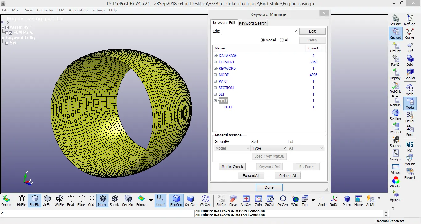
Part : Engine casing
Engine casing is the stationary part here, should not move from its location. The keywords for parts node and its node set are in single file. The material card for the same and its boundary conditions also having each .k file and it is directly included in the main. k file.
Part : Blades
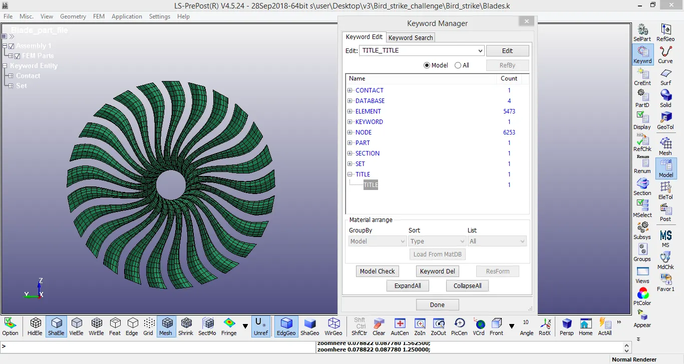
In this project, blades are the main component. It should rotate with some angular velocity 0.5mm/ms and material properties are slightly lower than bird so as to break earlier when the bird is making contact with it. The contact keyword is added to the blades part file. This will aloow the blade not to penetrate with adjacent blades. This is done by trial and error method.
Part : Hub
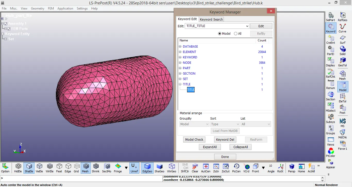
The hub is the solid component and it is meshed with trias. The hub is connected with blades so that the contact between blade and hub is not required. The hub is then rotate, if blades will rotate with respect to particular axis.
Part : Bird
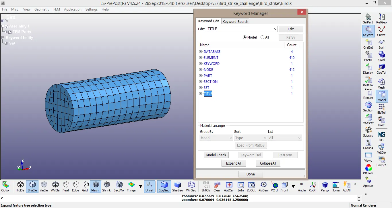
Bird is the shell component which is provided with 20mm/ms velocity and it hits the blades.
Material file :
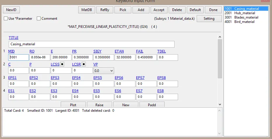
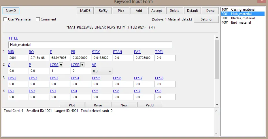
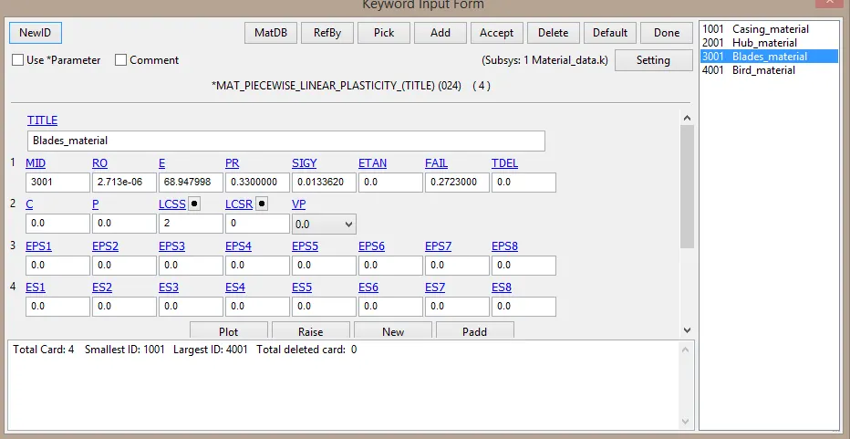
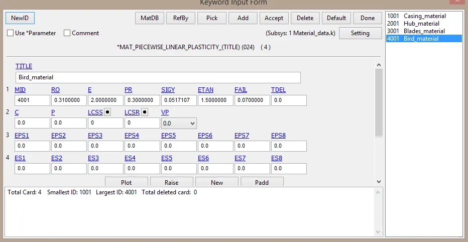
Material card for all four parts are in the above images in which all the material properties are described seperately in different cards. The load curve data is applicable only for blades and hub.
Boundary conditions :
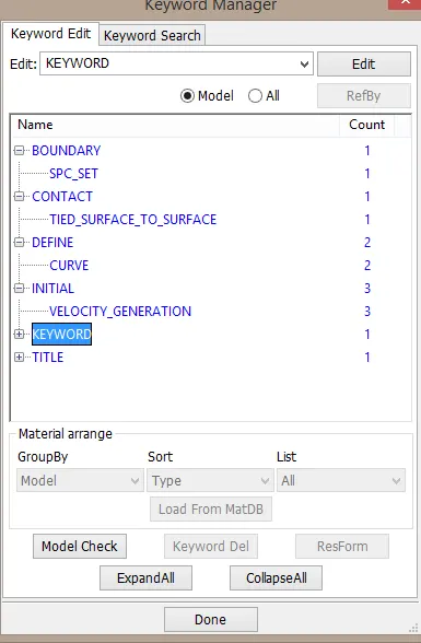
Spc set - for the nodes of an engine casing. The nodes are constrained in all directions.
Tied surface to surface - To connect blades with hub. This restricts the centrifugal effect on blades, if it begins its rotation.
Curve - Material curve for blades and hub.
Velocity generation - Instead of initial_velocity or prescribed_motion_node, here the velocity generation card is used. This is done by number of trial and errors methods by using initial_velocity or prescribed_motion_node. In velocity_generation card omega has to defined for both blades and hub.
Main .k file generation :
In main .k file, all the part files are called for the simulation. This is done by using include keyword and including part files, material file and boundary conditions to it. The 6 included files are
- Bird part .k file
- Blades part .k file
- Engine casing part .k file
- Hub part .k file
- Material .k file
- Boundary conditions .k file
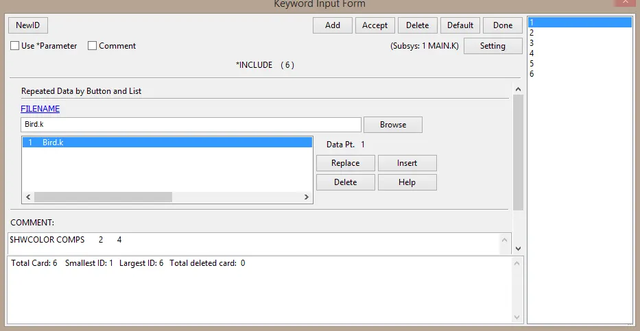

Simulation :
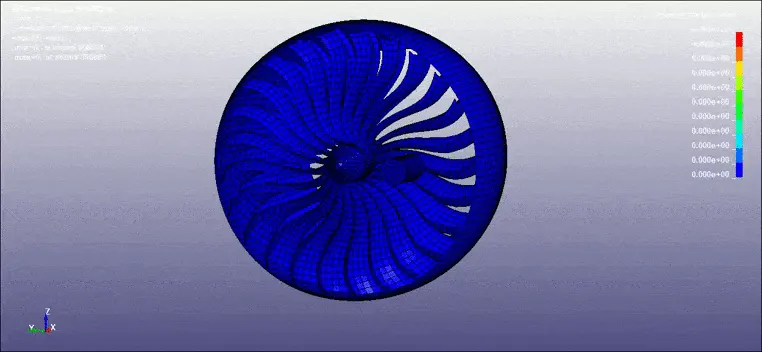
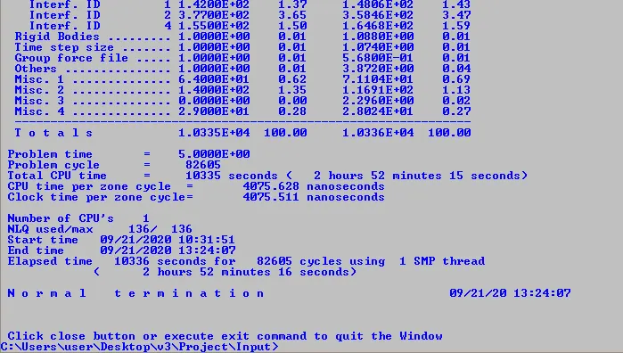
Output :
The simulation shows the blades are deforming and hub is dislocating. The proper and accurate method for this bird strike challenge is using SPH(Smoothed Particle Hydrodynamics) instead of shell component as bird. If SPH is move inside rotating blades, then the SPH will spread like fluid properties and the corresponding deformation could see in the blades. The failure value for blades and bird are applied. The elements failing in this simulation is eliminated.
CONCLUSION :
Thus the bird strike challenge is done using shell component of bird. The corresponding deformations are also listed above. The main objective of including part files in main .k file is done like an industry project level. Some of the learning outcomes are
- How to include the files in main .k file?
- Failure criteria for the elements.
- Different velocity cards by trial and error method.