Frontal crash of the car - Crashworthiness using Hyper Mesh and Radioss
OBJECTIVE :
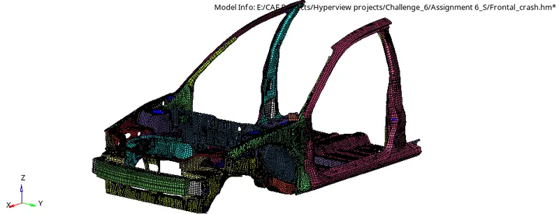
To construct the required cards for the BIW of the car to undergo frontal crash. Neon BIW consists of 75 components and half of the BIW in its length. COG has to place in the position to avoid the fluctuation in weightage of the BIW. Sectional, axial and cross sectional forces of some desired components has to extract for the safety level of BIW.
PROCEDURE :
Unit system
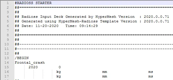
The unit system for the magnitude of any forces or values used in the frontal crash test is in accordance with Kg-mm-ms.
Interface
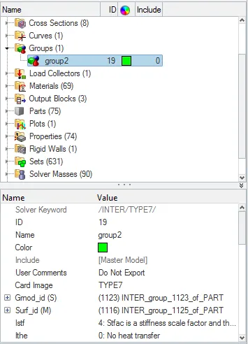
The type 7 interface is used for the BIW components. Instead of type 11, type 7 interface is used here. This is because type 11 interface is only edge to edge contact. Type 7 is a sliding contact which could enable the possible impact between the set of nodes and the master surface.

Penetrations check
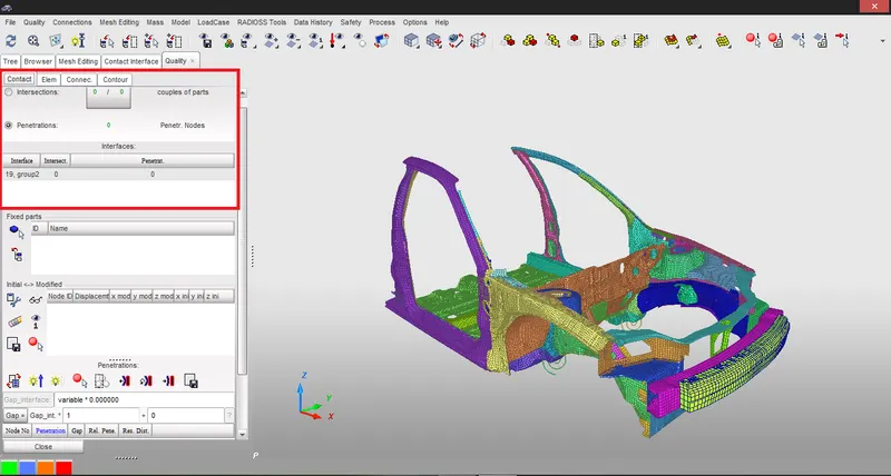
Penetrations check for the neon BIW is done on HyperCrash. In which the frontal crash geometry in imported to HyperCrash and then check has been done for the penetrations of any component into other. That means the gap between two components in the system should be available. For shell elements, if two rectangular slab of thickness 6mm lying parellely to each other the gap between two shells should be greater than or equal to 6mm. This makes the components not to overlap when it changed to 3D structure in real time. If the thickness is less than 6mm then the checks shows an error.
Rigidwall
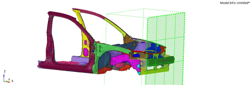
Rigidwall is created in front of the assembly so as to do the frontal crash. The location of the rigidwall and the direction in which the velocity is applied for the components decide the type of crash test. In this case, the velocity is applied for the components in X-axis and the rigid wall is placed respect to that. The rigidwall is created in reference to the node from the bumper of the BIW. The type of the rigidwall is infinite plane.
Initial velocity
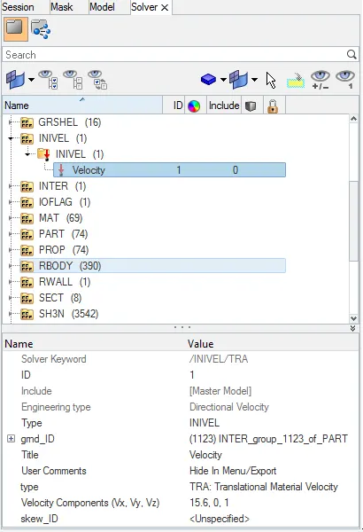
Initial velocity is the speed of the components by which it will hit the rigidwall. The average speed of the vehicle maintained as 35miles per hour in any cases. In frontal crash, the unit system followed here is Kg-mm-ms. Miles per hour is converted to the mm-ms. In this crash simulation, 15.6mm/ms is applied to the nodes of the components.
Model check
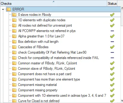
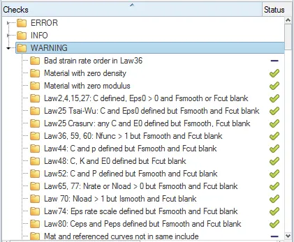
Model check is done for the entire component to find out the errors and warnings which are in the model. If errors are available and not made ok, the simulation will not run. Warnings will not create much impact in the simulation.
Timestep and run time
The most important things in the simulation is the total run time and timestep in which the results has to write as .h3d file. For the crash test the maximum run time is 150ms since within this time the crash will happen. For tensile test the run time will be higher. Timestep is within the total run time. Here the total run time is 80ms.
OUTPUT :
Sectional force in the rails at location of indicated node 174247
RAIL 1 :
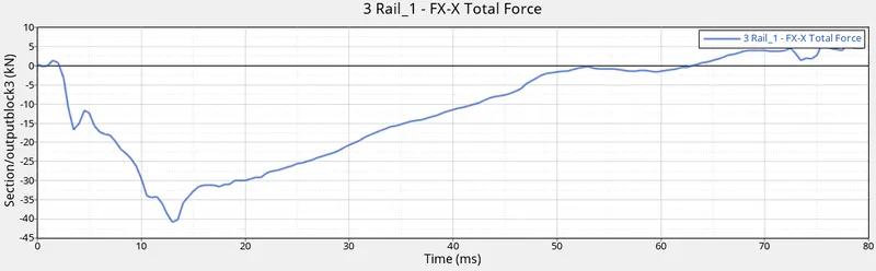
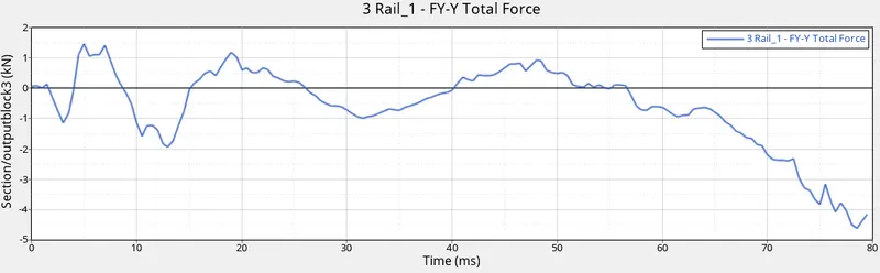
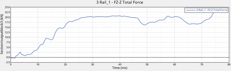
In the above three images initially the X-X sectional foces moves to negative side which depicts the force is done on the opposite side to the applied force. Y-Y sectional forces occur in both positive and negative directions which depicts that the force is applied over it from all the directions by different components due to collision of nearby components.
RAIL 2 :
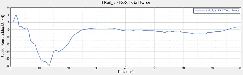
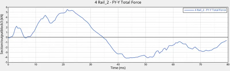
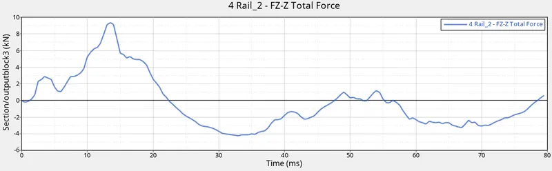
The forces on the rail 2 component is entirely different when compared with rail 1. Even though the BIW is symmetrical, the force generated on both the rails are different.
Shotgun cross sectional forces
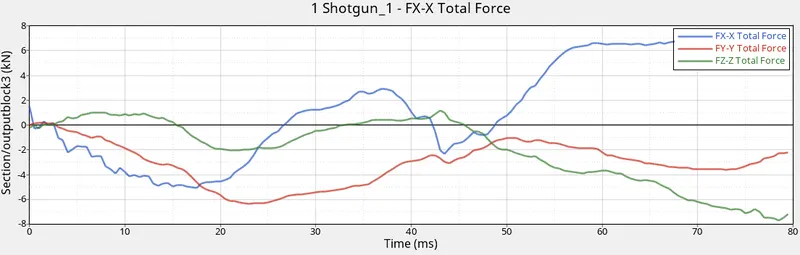
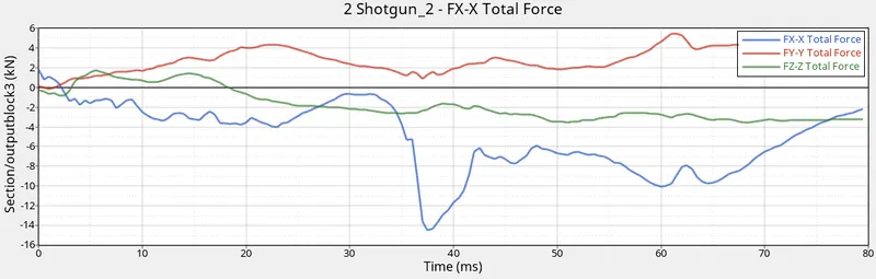
A pillar cross section
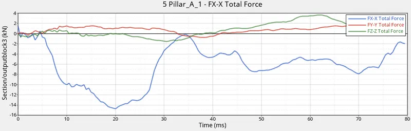
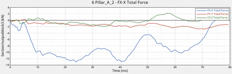
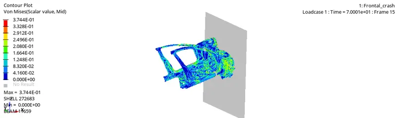
The force over both pillars in Z direction are higher than in other axes. Because the curved BIW which connects pillar to the engine locating parts has pressed the pillars towards downwards. This is because the force over both pillars in Z direction is much higher. After hitting rigidwall it happened.
Intrusions on the dash wall 66695,66244
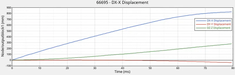
The node 66695 is moved to a distance of nearly 810mm from its initial position. And it moved 280mm in Y axis. In Z direction it moves downwards to 40mm.
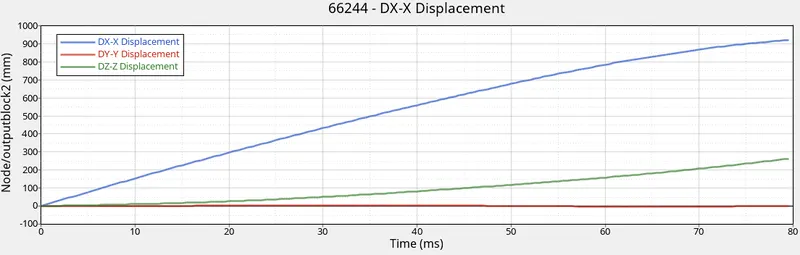
The node 66244 is moved nearly 910mm in X direction and 250mm in Y direction and 0mm in Z direction.
CONCLUSION :
Thus the frontal crash of the car is simulated successfully with no errors. The deformations occur mostly on the front portion of the car. The BIW is good in a way that it not affect the driven cabin much. The limitations here are the real frontal crash could not found out due to half the car FEA is simulated. This can be clearly visible that the front cabin is moving downwards after hitting.
If the entire FEA of car is simulated, the front cabin would not move downwards. Due to this some of the impact from frontal portion will penetrated to the front cabin. This will leads to more deformation of below mentioned car parts
- CH-CBN-FLOORBRD-FT
- CH-A-PILLAR-B-I-L
- CH-A-PILLAR-B-I-R
- CH-CBN-OUTER-L
- CH-CBN-OUTER-R