Rear suspension shell and solid meshing - ANSA
OBJECTIVE : To check the geometrical errors on the given suspension system and mesh the component with given quality criteria using tetra elements where the thickness is not uniform and with mixed elements where the thickness is uniform and less than 5mm.
PROCEDURE :
- Geometrical errors check up
- Mid surface
- Shell mesh
- Volume mesh
- Quality criteria check up
- Connections
- Thickness assignation
- Presentation views
Geometrical errors check up
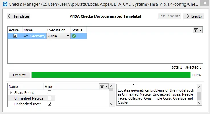
The given suspension system is imported in ANSA pre processing software. Initially the geometry should checked for errors. There are some triple cons, unchecked faces, single cons and needle faces. The triple cons and single cons are cleared by manual work on the model. Some of the unchecked faces are cleared by manual and by ANSA itself.
Mid surface
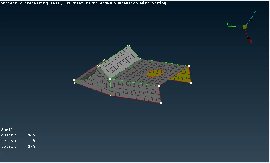
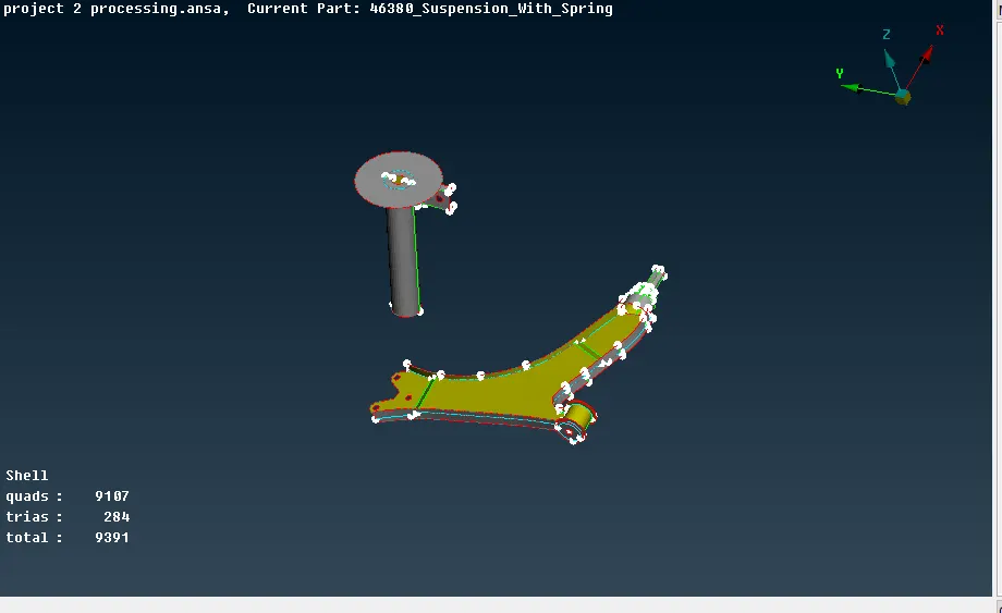
Suspension system almost consists of solid components with varying thickness. Some supporting components are there which might fall under 2D mesh category. And the shell mesh is done only for thickness below 5mm. For the mid surface extraction, skin tool is used since the parts are simpler.
Volume mesh
The volume mesh is nothing but shell mesh the component with trias and ortho trias and mesh with tetra rapid or tetra FEM. The finalize component will have only tetra elements as volume. Almost 80 percent of the parts of suspension system consists of volume mesh since there are number of thickness varying solid components.
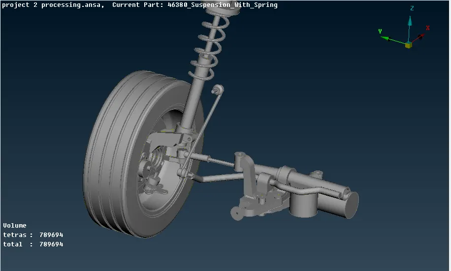 The above image depicts only the volume elements.
- The shell elements are released from the CAD and made as seperate FE.
- The trias are placed at the flat faces.On the other hand the ortho trias are placed on curved faces. Ortho trias provided a better shell mesh on the curved faces than trias. The target elements length used is 7.5mm.
- For better mesh tools like improve, reconstruct and smooth are used. Split and join tool restricts the usage since it leads to the creation of some quads elements there.
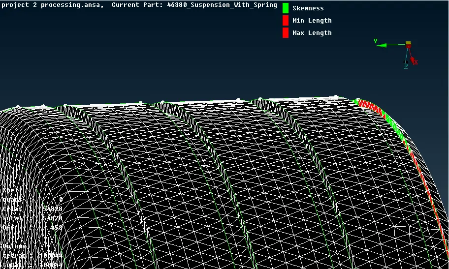
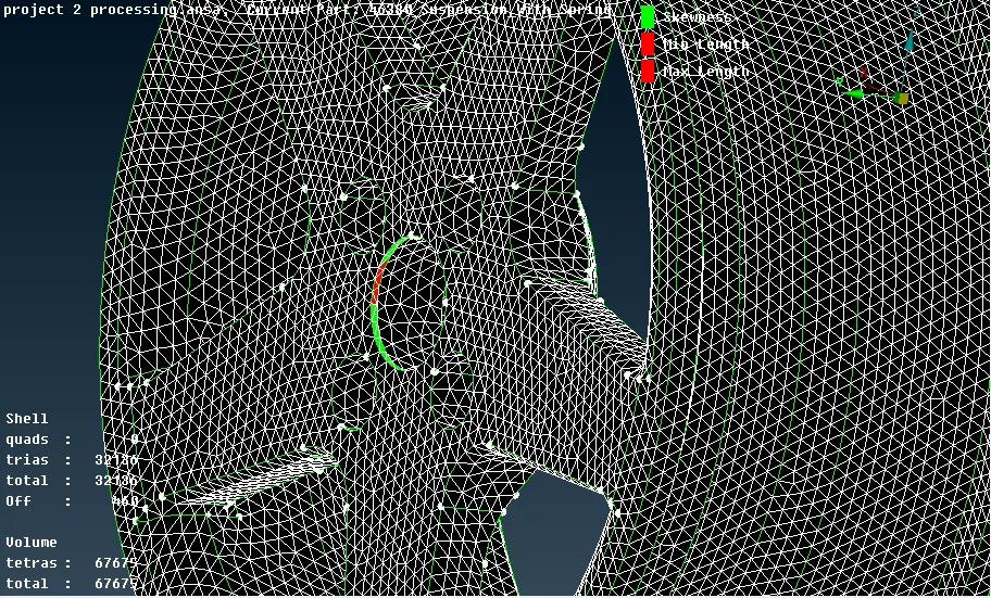
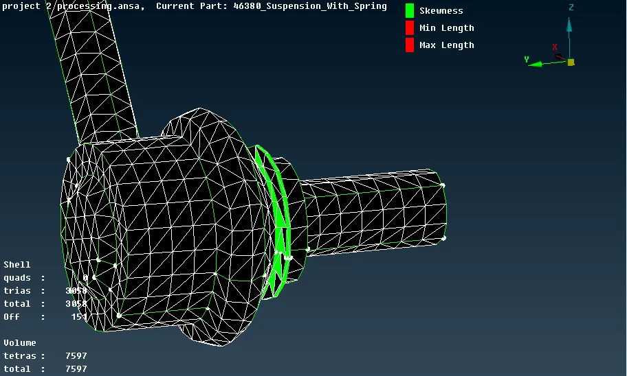
- Some faces have length lesser than minimum element length. At there the elements are failuring and there are no chances to make it ok.
Quality criteria check up
The quality criteria is an essential one like geometry check up.
- It is mandatory to check up the quality and to clear out the failing elements under specific criteria.
- Here as per the mention at above paragraph, there are some small faces or macros that are failing under minimum element length criteria. To clear it out, some of the features have to be toggled or suppresed. Due to the violation in geometry, no macros or faces are toggled.
- The elements failing under minimum length category are left as failure case. The remedy for this is to decrease the minimum element length.
- Those faces are in tyre, rim and guiding rod.
Connections
- After the mesh on both 2D and 3D category, moved to the connections which made the parts of the suspension system to join each other for simulation process.
- Here the simple connections are made by using RBE2 elements since there are no available of bolt or weld geometry.
- At most well known places, RBE3-HEXA-RBE3 elements are placed since it is one of the major connection.
- The weld elements are not placed at anywhere because suspension system is almost a mechanism to rotate all the parts at particular axis.
- Since the connection between the tyre an rim is not rigid and felxible at load varying situations, weather strip at side door mirror concept connections are made here. RBE3-CBUSH-RBE3 elements are placed between tyre and rim.
- Caliper and brake disc have no connection at all other than manual movement of caliper toward brake disc. In there, no connections are made between them.
- Other parts of the suspension system are connected by either bolts or using RBE2 elements.
Thickness assignation
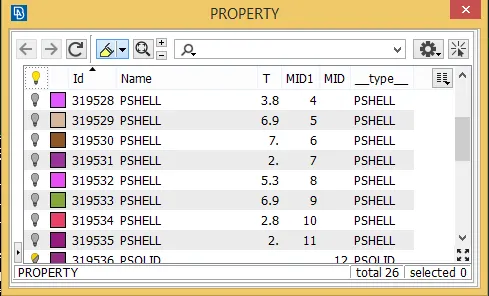
The thickness for the mid surfaces taken are applied at property card(PID).
Presentation views
After this all, presentation views are performed under quality criteria module to check for the proper appling of thickness for mid surfaces.
LEARNING OUTCOME
- How to volume mesh the component?
- How to check the mid surfaces having proper thickness by presentation view?
CONCLUSION
Thus the given suspension system is entirely meshed by 2D and 3D mesh and connections deployed between it's parts and thickness assigned to mid surfaces.
https://drive.google.com/file/d/14K92A-XvY8HxX-uBiFhkHi-P-bmjvIzA/view?usp=sharing