Week-7 : Converting a detailed engine model to a FRM model
In this challenge, we will see how the detailed modelling model functions against a Fast running model operate and how to convert a detailed model to FRM model and we will run both the models and compare the accuracy of FRM to detailed model and compare the CPU time consumed to run the same model and draw conclusions about the usability and approaches towards the FRM model.
FRM model:
FRMs execute much more rapidly than the typical detailed GT-POWER engine model, and are ideal for integrating with other vehicle systems where an accurate and predictive engine plant model is desired and where computational speed is critical. FRMs adapt to changing conditions (e.g. valve timing, spark/injection timing, turbo lag, external temperature, altitude, cooling system conditions, etc.) without the need to apply non-physical correction factors. Whether studying changes to ambient conditions, or simulating events that are heavily transient in nature, FRMs will maintain the predictive capabilities of a detailed engine model while allowing for the fast computational speeds that are expected when performing drive cycle analysis and other transient-focused simulations.
Some examples of applications that are ideal for FRMs are:
- ECU Modeling (including HiL) – where a fast-running and transient-capable engine model is essential for optimizing ECU strategy
- Engine + Drivetrain/Vehicle – where accurate torque pulsations are key for optimizing drivetrain design and strategy
- Vehicle Thermal Management modeling, where the engine provides the heat to the cooling system, and the cooling system behavior feeds back into the engine performance predictions (great for simulating off-ambient conditions)
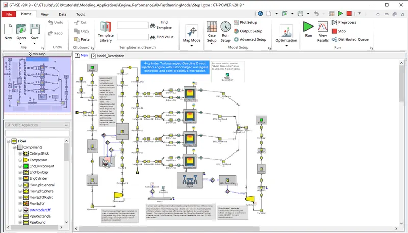
detailed model:
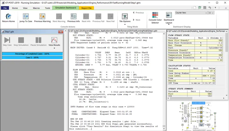
results for detailed model:
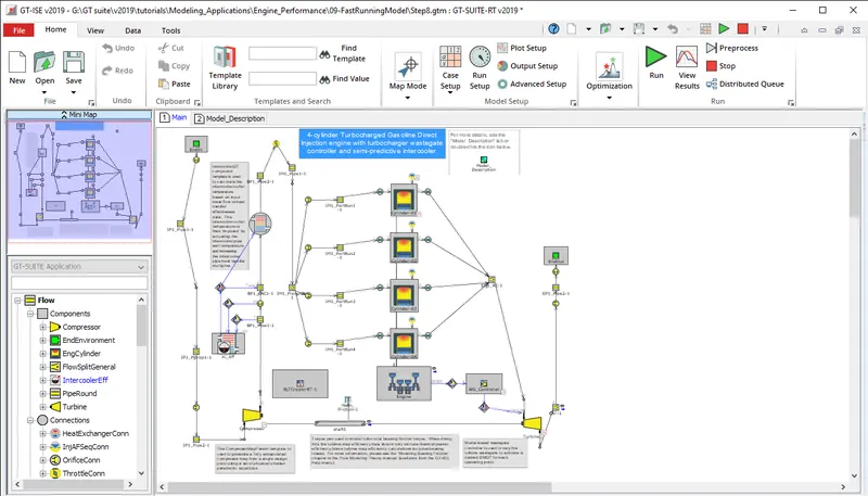
FRM model after conversion:
we can see the inlets are now converted to a single subunit where the data is fed to all 4 cylinder and exhaust ports are converted to a single point this conversion saves a lot of computational time.
Build FRM Model for the following configuration using FRM builder approach
- Bore 102 mm stroke 115 mm CR 17
- No of cylinder 6
- CI engine
- Twin Scroll Turbine
- GT Controller
below is the model of an FRM model with the following given data.
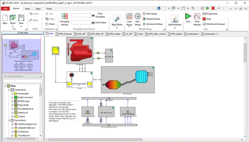
an overview of the FRM model which was generated:
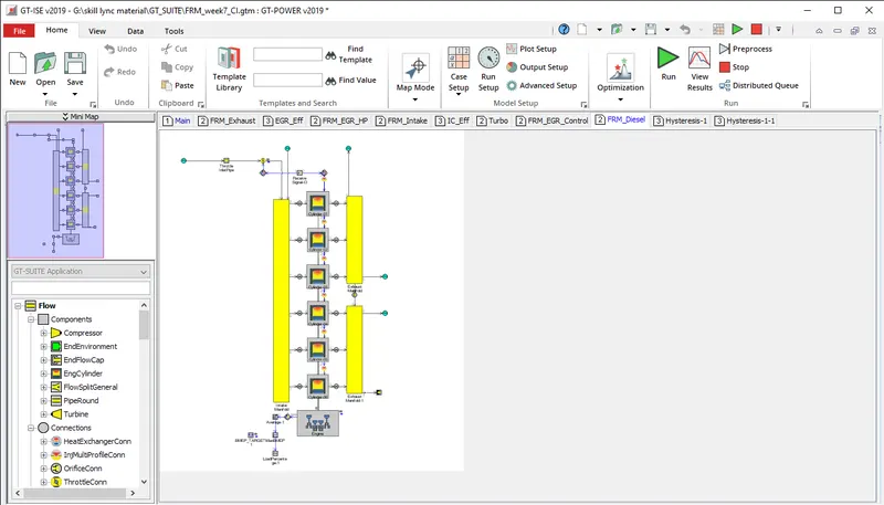
FRM diesel sub system:
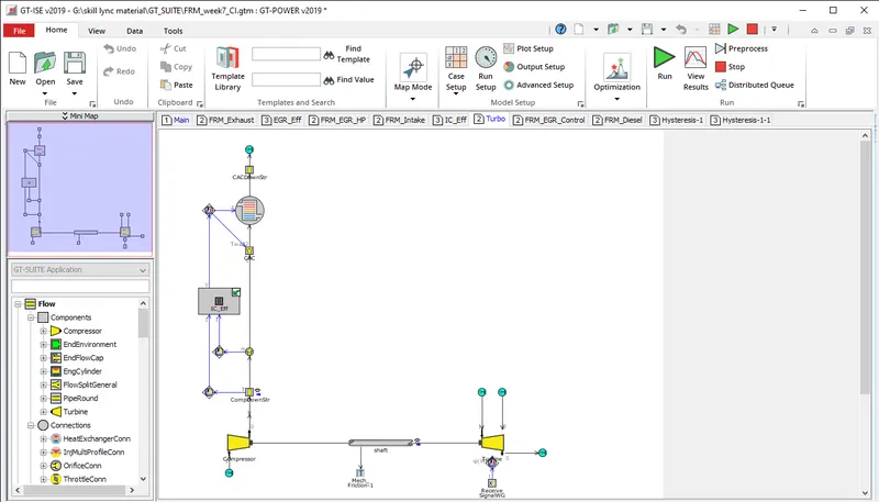
below we can see the following data after running 25 cases the total CPU time was 37.24 seconds.
results:
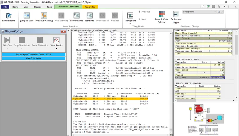
we can see all the values of case 1 from the FRM model
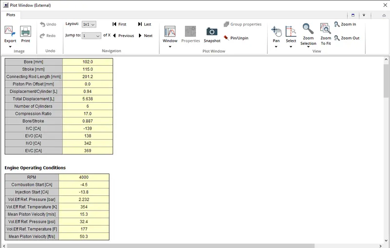
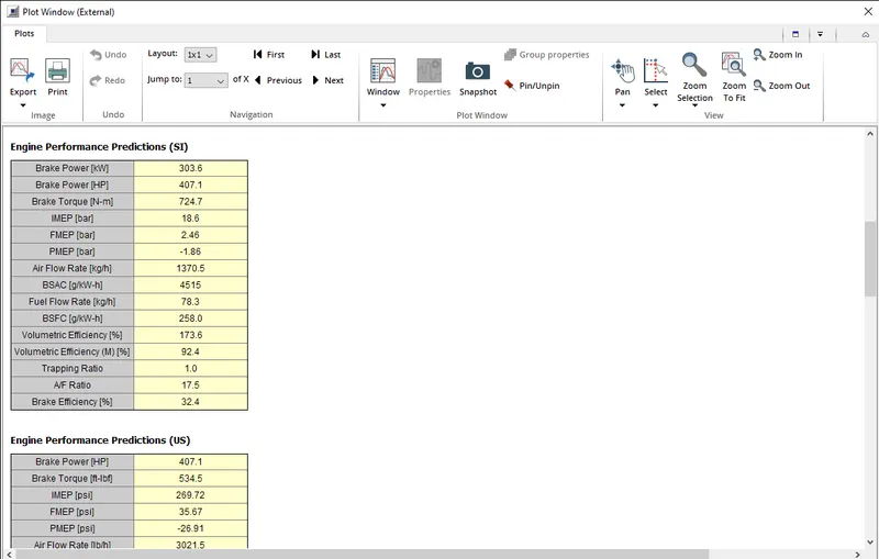
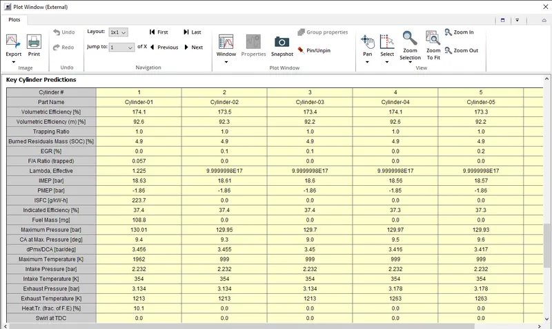
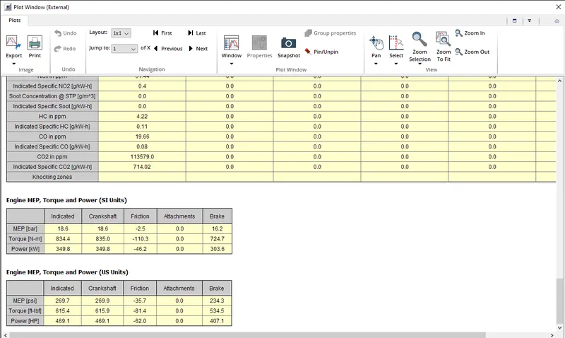
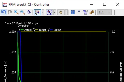
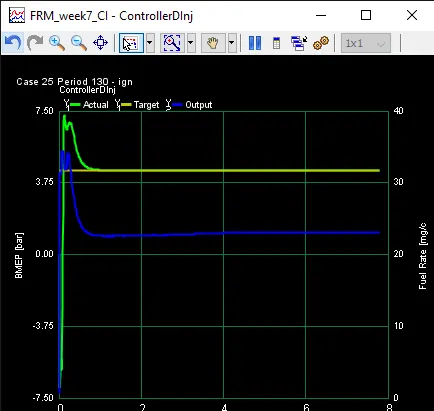
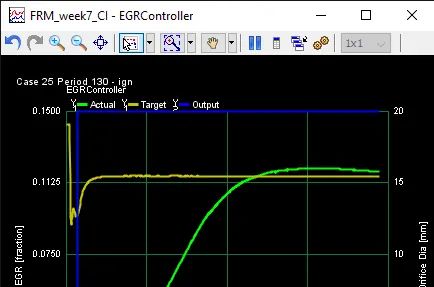
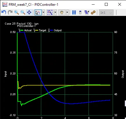
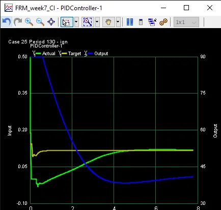
through this model we can also generate plots for better understanding of the model under observation: