Assignment 1
1) Explore the GUI of GT SUITE and list down modules available with a brief description.
INTRODUCTION TO GT SUITE:
The foundation of GT-SUITE is a versatile multi-physics platform for constructing models of general systems based on many underlying fundamental libraries:
1) GT-ISE - GT-ISE is the main interface where models are built, simulation settings are declared, and simulations (both single and batch) are launched. It is an environment where various components are brought into a project map and connected together linking the entire model as a whole.
2) COOL 3D -COOL3D tool allows for 3D model building and automatic export of underhood cooling module models. GT-SUITE models can be used to analyze pressure drop, flow distribution, and thermal performance of liquid circuits that cool heat-generating components. GT-SUITE is also used to optimize airflow and heat transfer in the underhood cooling module where heat is rejected to ambient.
3) GEM 3D -GEM3D is a 3D graphical pre-processor that combines building and importing tools used to create 1D GT-SUITE models from 3D geometries.
- GEM3D can be used to build models from primitive components like pipes, flow splits, shells, catalysts, pumps, etc.
- GEM3D can also be used to import 3D CAD models from other applications, especially GT-SPACECLAIM. Once imported it can be used as a “characterizer” to automatically find effective lengths, diameters, bends, volumes, etc. of complex shapes, and convert them into GT-SUITE equivalent parts, such as pipes and flow splits
- Not only can 3D models be imported and characterized, but additional components can also be added to these models in GEM3D.
- The design is general such that GEM3D can be used for many applications including engine performance, acoustics (intake and exhaust systems), lubrication, cooling systems, hydraulics, cranktrains, and more.
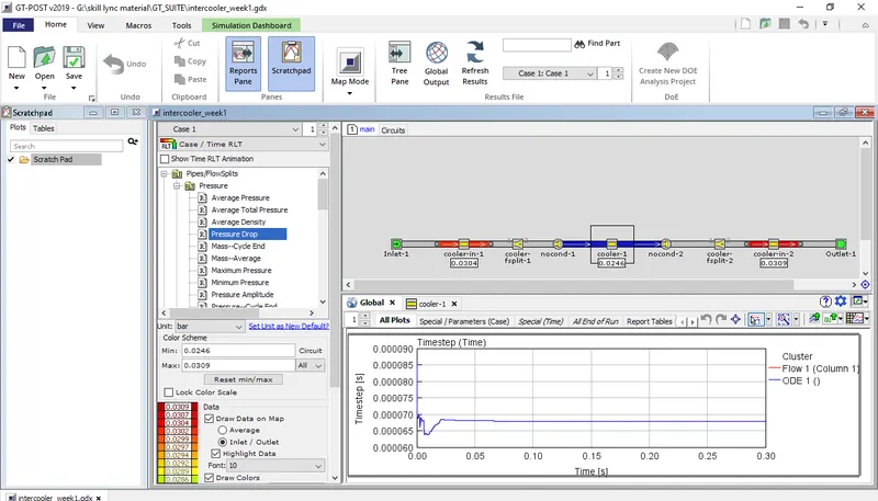
4) GT-POST- Once a simulation is complete, results are viewed in GT-POST, a graphical interface that enables viewing and manipulating of the data collected from the simulation. GT-POST contains the following functions and more:
- Graphically based data post-processing
- Quickly generate 2-D and 3-D plots
- Combine data from different cases, simulations, or tests into a single plot
- Re-usable post-processing templates allow instant cross-plotting of results from different
simulations - Implicit links to ASCII/Excel files with database capabilities for fast and flexible access to
measurement data. - Import or Export data to/from ASCII or MS/EXCEL files
- Perform various math operations on data in all plots (sum, difference, integral, derivative, FFT…)
- Animation of transient processes
- User-definable tabular output of computed results
which include:
- Cam design tool for creating/modifying cam profiles, using one of many methods: constrained polynomials, intuitive b-spline control of acceleration, or hybrid spline with low order constants/slopes/quadratics connected by splines.
- Dimension-by-dimension visual setup of the valvetrain mechanism. All 5 standard valvetrain types are supported, and profile entered can be cam shape or valve lift profile
- Kinematic and Quasi-Dynamic (Elasto-Kinematic) analysis can be run and viewed directly from the VTDESIGN interface (and updated dynamically with any cam profile changes). CNC cutting tool path can also be calculated from kinematics.
- Spring design tool to create and modify spring shapes, using geometry (axial height vs. helix angle) or force vs. displacement curves. Spring free stroke, solid height, Eigenmode analysis, and fatigue safety factor are all calculated within the interface.
2. Locate following settings:
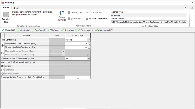
- Time control flag (5 Marks)
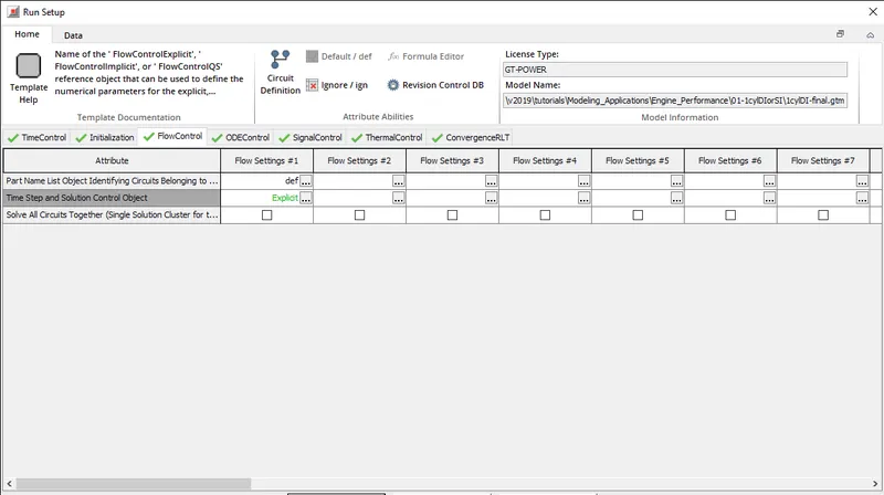
- Time step and solution control (5 Marks)
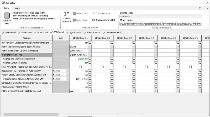
- Integrator/Solver type (5 Marks)
- Time control flag
2) Time step and solution control
3)Integrator/Solver type
3.Explore intercooler tutorial and note down all settings of:
- Run setup (5 Marks)
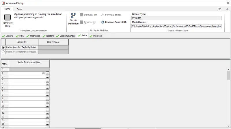
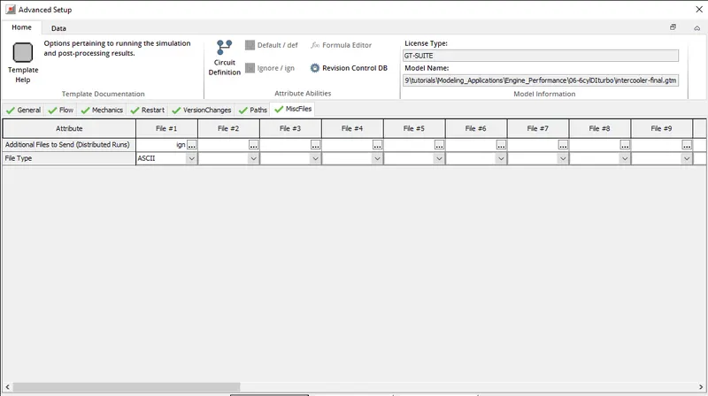
- Advanced setup (5 Marks)
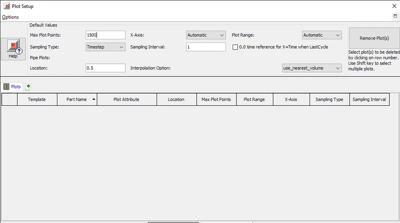
- Plot setup (5 Marks)
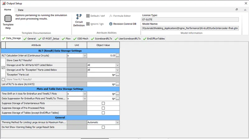
- Output setup (5 Marks)
RUN SETUP:
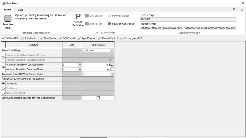
1)Time control:This folder is used to define the simulation duration and time-controlling variables. The attributes in this folder must be defined for all simulations.
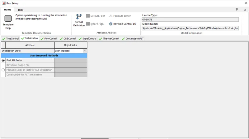
2)Initialization: This folder defines the settings about how the initial conditions will be imposed for the simulation. Every state variable must be initialized at time=0.0 of the simulation. For example, flow components must be initialized with pressure, temperature, and composition; flow connections must be initialized with velocity or mass flow rate; shafts must be initialized with rotational speed; other mechanical parts position; and some control components with a "State" value.
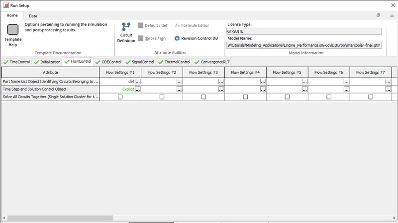
3)Flow control: This folder is used to define independent flow “circuits” within the model and to specify solver settings related to modeling of flow for these circuits. A circuit is defined as an interconnected group of flow components, typically sharing the same fluid.
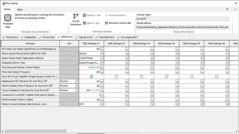
ODE control: This folder is used to define independent “ODE circuits” within the model and to specify solver settings related to these circuits. An ODE circuit can be an interconnected group of mechanical, electrical, magnetic, or control parts.
signal control:This folder can optionally be used to define independent Control "circuits" within the model and to specify solver settings related to modeling these circuits. A circuit is defined as an interconnected group of controls components that share the same time step.
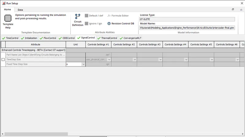
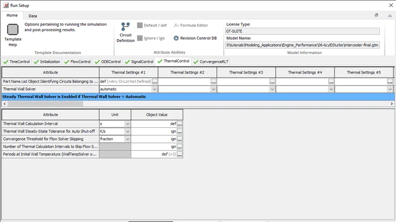
Thermal control: This folder controls the thermal wall (structure) solver only, which includes the wall material of pipes and flowsplits, thermal mass/block/node, aftertreatment, and finite element objects. This folder does not control the thermal calculation of the fluid, which cannot be disabled.
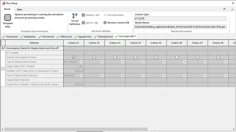
Convergence RLT: This folder can optionally be used to impose one or more steady-state criteria (up to a maximum of 10) that depend on RLT variables in a simulation. When active, these checks are additional criteria that must be met in addition to any other convergence checks (i.e. see FlowControl, ThermalControl and ODEControl folders and a number of controller templates) for a simulation to be considered at steady-state and thus eligible for an early finish
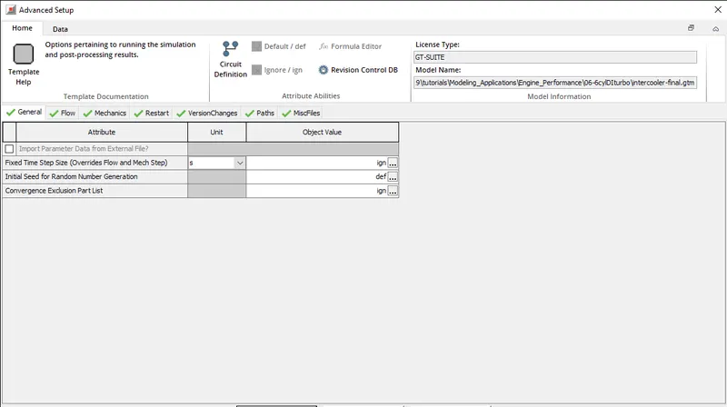
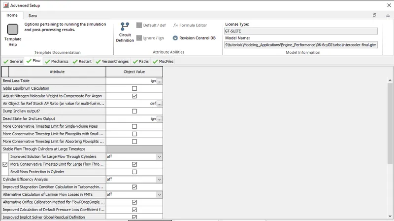
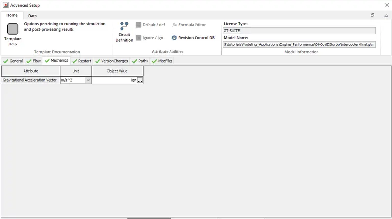
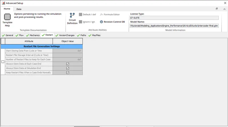
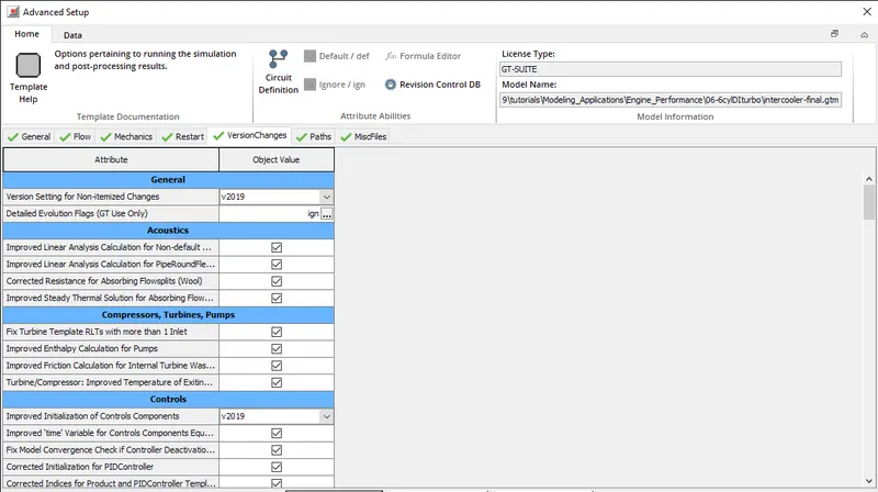
Data Storage: This folder can be used to optionally suppress certain GT-SUITE output in simulations where not all results are interesting. These options can be especially useful for models that are very large (i.e. many parts), span very long durations (i.e. many cycles), or have many cases, such as a DOE run. In many of these larger models, the amount of data that would be saved if every output option is fully on would be prohibitively large, negatively affecting hard disk utilization and post-processing speed.
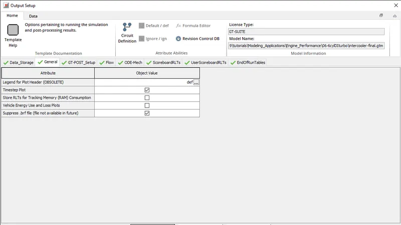
General :
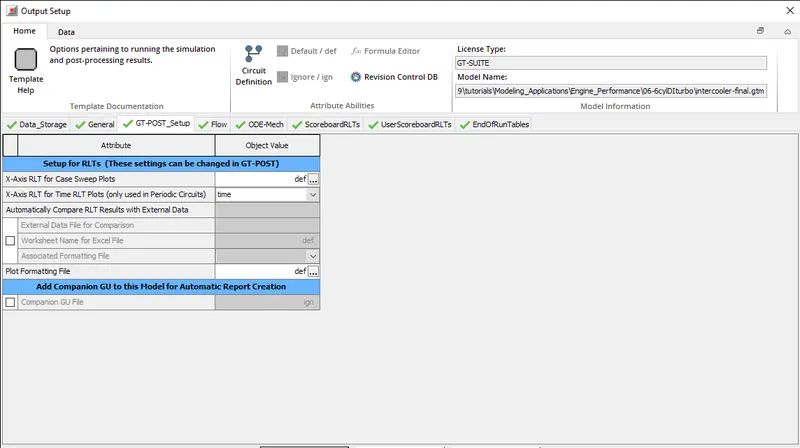
GT-POST Setup:
This folder enables some settings for the GT-POST post-processing tool to be defined before the simulation starts. All of these settings can be changed in GT-POST itself, but especially if a given model will be run and rerun many times, it is more convenient to specify the values once here in this folder so that the results are set up for optimal post-processing in GT-POST immediately when the results are opened.
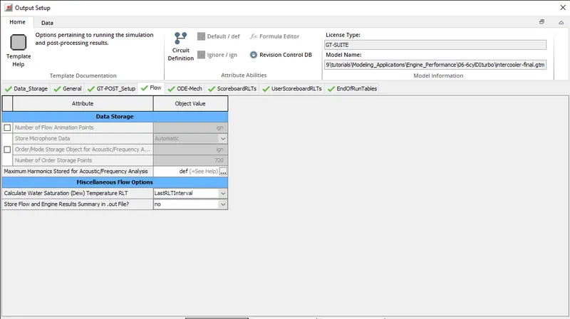
Flow
This folder allows the user to optionally store and specify settings for various outputs that can be viewed after the simulation has run in GT-POST.
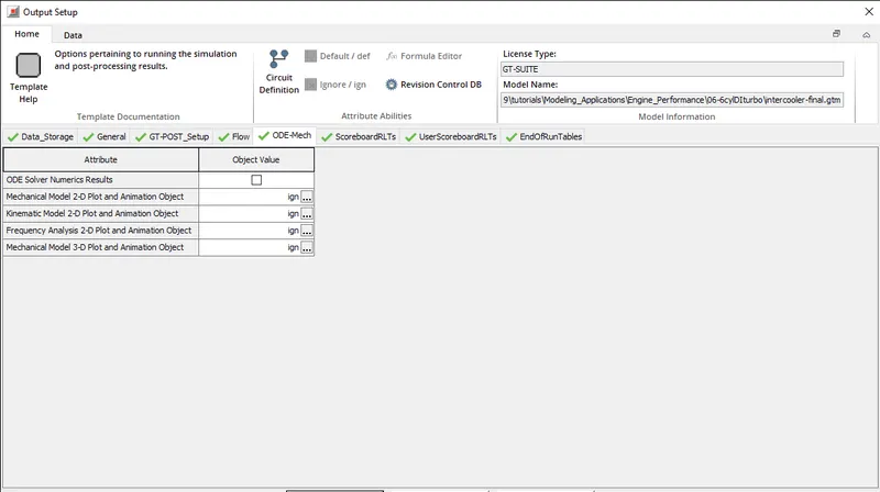
ODE-Mech
This folder allows the user to optionally store and specify settings for various outputs that can be viewed after the simulation has run in GT-POST.
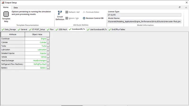
ScoreboardRLTs
This folder allows the user to define sets of RLTs that will be reported for functional groups of templates in "default scoreboards" within the solver UI at runtime. Solver UI scoreboards are divided into two categories, default and user. This folder allows the user to modify and control the former.
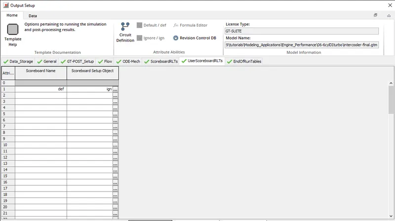
UserScoreboardRLTs
This folder, similar to the ScoreboardRLTs folder, is used to define the data displayed at runtime in the solver UI. While the ScoreboardRLTs folder allows the user to modify GT-provided "default scoreboards," this folder allows the building of custom, user scoreboards. The definition comprises of a scoreboard name and an associated reference object which contains a list or RLTs to be reported in the grouping.
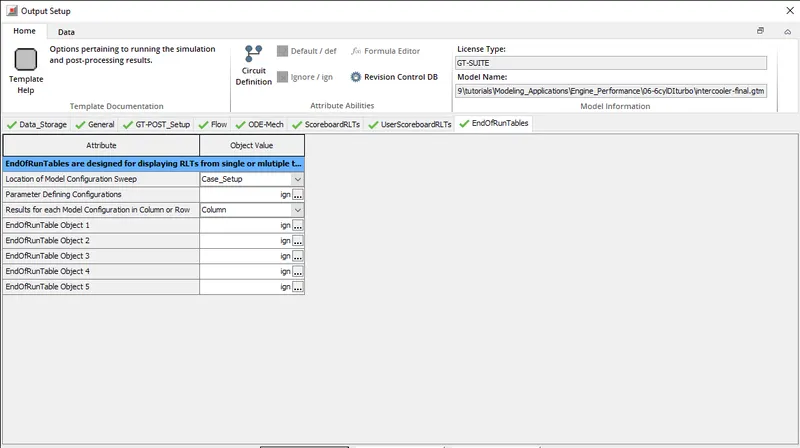
EndOfRunTables - RLT Summary Tables
This feature is used to generate a 2 dimensional table of RLTs. One dimension of the table is identified by a corresponding "Configuration" for which unique instances are associated with either case numbers in CaseSetup or DOE Experiments in DOE Setup. The second dimension of this table corresponds to a unique set of "Test" cases to be performed for each "Configuration". The user is allowed to define up to 5 unique tables which may consolidate specific types of "Test" cases for a common set of "Configurations".
4. Problem: (50 Marks)
Given
- Diameter of cooler inlet and outlet pipe= 50 mm
- Length of the CAC= 1000 mm
- Inlet mass flow rate = 1200 kg/ h at 100 degC
- Outlet pressure 2 bar at 30 deg C
- Calculate the total heat transfer at Charge air cooler (CAC)
- Calculate pressure drop across CAC
Open the intercooler model and we need to change the following parameters
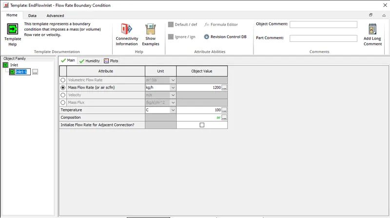
1) Open the end flow inlet model and we need to change the mass flow rate to 1200 kg/h and change the temperature to 100 degC
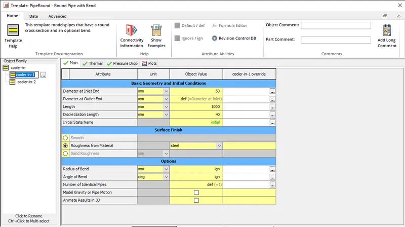
2) open the pipe round folder and change the diameter of inlet and outlet to 50mm and the length of the pipe to 1000mm
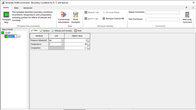
3) Open the EndEnvironment folder and change the outer pressure to 2 bars and temperature to 30 degC
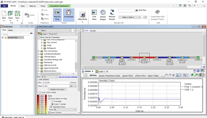
now simulate the model and open GT-Post for data analysis
we obtain the following results:
Total heat transfer at Charge air cooler:
Pressure Drop across Charge air cooler :