Week-7 Challenge: DC Motor Control
1. A. Explain a MATLAB demo model named ‘Speed control of a DC motor using BJT H-bridge’.
Ans:-
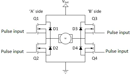
An H-bridge is a simple circuit that lets you control a DC motor to go backward or forward.
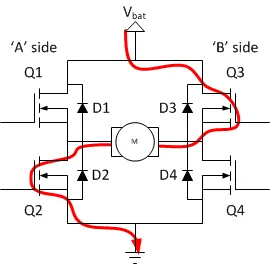
An H-bridge is built of four switches that control the flow of current to a load. In the image above, the load is the M connecting the two sets of switches. Using one current source, you can drive current in two directions by closing two switches.
The Bipolar Junction Transistor (BJT) when used for power switching applications, operates as an IGBT. When it is conducting (BJT operating in the saturated region), a forward voltage Vf is developed between collector and emitter (in the range of 1 V). Therefore, the IGBT block can be used to model the BJT device.The IGBT block does not simulate the gate current controlling the BJT or IGBT. The switch is controlled by a Simulink signal (1/0).
The DC motor uses the preset model (5 HP 24V 1750 rpm). It simulates a fan type load (where Load torque is proportional to square of speed). The armature mean voltage can be varied from 0 to 240 V when the duty cycle (specified in the Pulse Generator block) is varied from 0 to 100%.The H-bridge consists of four BJT/Diode pairs (BJT simulated by IGBT models).
Two transistors are switched simultaneously: Q1 and Q4 or Q2 and Q3. When Q1 and Q4 are fired, a positive voltage is applied to the motor and diodes D2-D3 operate as free-wheeling diodes when Q1 and Q4 are switched off. When Q2 and Q3 are fired, a negative voltage is applied to the motor and diodes D1-D4 operate as free-wheeling diodes when Q2 and Q3 are switched off.
- The basic operating mode of an H-bridge is fairly simple: if Q1 and Q4 are turned on, the left lead of the motor will be connected to the power supply, while the right lead is connected to ground. Current starts flowing through the motor which energizes the motor in (let’s say) the forward direction and the motor shaft starts spinning.
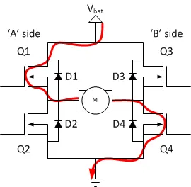
- If Q2 and Q3 are turned on, the reverse will happen, the motor gets energized in the reverse direction, and the shaft will start spinning backwards.
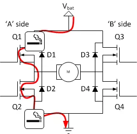
- In a bridge, you should never ever close both Q1 and Q2 (or Q3 and Q4) at the same time. If you did that, you just have created a really low-resistance path between power and GND, effectively short-circuiting your power supply. This condition is called ‘shoot-through’ and is an almost guaranteed way to quickly destroy your bridge, or something else in your circuit.
The Bipolar Junction Transistor (BJT) when used for power switching applications, operates as an IGBT. When it is conducting (BJT operating in the saturated region), a forward voltage Vf is developed between collector and emitter (in the range of 1 V). Therefore, the IGBT block can be used to model the BJT device.
Simulink model:
-The DC motor uses the preset model (5 HP 24V 1750 rpm). It simulates a fan type load (where Load torque is proportional to square of speed).
-The armature mean voltage can be varied from 0 to 240 V when the duty cycle (specified in the Pulse Generator block) is varied from 0 to 100%.
-The H-bridge consists of four BJT/Diode pairs (BJT simulated by IGBT models). Two transistors are switched simultaneously: Q1 and Q4 or Q2 and Q3.
-When Q1 and Q4 are fired, a positive voltage is applied to the motor and diodes D2-D3 operate as free-wheeling diodes when Q1 and Q4 are switched off. When Q2 and Q3 are fired, a negative voltage is applied to the motor and diodes D1-D4 operate as free-wheeling diodes when Q2 and Q3 are switched off.
B. Comment on the armature current shoot-up from the scope results.
-Armature current shoot-up at the starting of the armature current a sudden rise in the waveform the motor starts in the positive direction with a duty cycle of 75%. At t= 0.5 sec the armature voltage is suddenly reversed and the motor runs in the negative direction.
scope shows motor speed, armature current and load torque and 'Currents' shows currents flowing in BJT Q3 and diode D3.
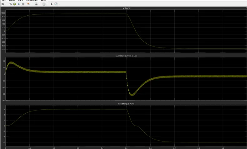
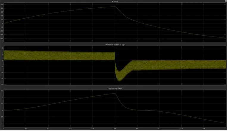
Due to duty cycle the current deviation is observed in the result, when the duty cycle is changed to 50 from 75 we can observe that the amount of deviation is also reduced.
C. Refer to the help section of ‘The Four-Quadrant Chopper DC Drive (DC7) block’. Compare it with the H-bridge model.
Ans:-
| Four Quadrant chopper | H-bridge model | |
| 1. | The motor can be operated in all the four different modes (forward motoring,reverse motoring ,forward braking and reverse braking) | In this model we have only two modes forward and reverese by changing the direction of motor. |
| 2. | vehicle control is in better way | In this the vehicle control is less. |
| 3. | Regenerative braking can be achieved | In this regenerative braking is not possible. |
| 4. | The signals given to the four quadrant operation are discrete(non continuous) | signals are continuous. |
| 5. | The four-quadrant chopper widely usedin the automobile application for the control of DC motor speed and direction. | The H-bridge is used in the robotics and electro-mechanical devices to control the speed and direction of the DC motor at low level speed. |
2. Develop a 2-quadrant chopper using simulink & explain the working of the same with the relevant results. (Refer to article - Multiquadrant operation of motor )
Ans:-
Two Quadrant Chopper
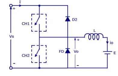
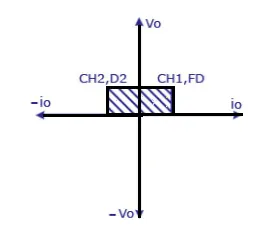
In this type of Chopper, the average voltage will be always positive but the average load current might be positive or negative. The two Switches CH1 and CH2 should not be turned on simultaneously as the combined action may cause a short circuit in supply lines. For regenerative braking and motoring these type of chopper configuration is used.
We will always get a positive output voltage V0 as the freewheeling diode FD is present across the load. When the chopper CH1 is on the current flows from source to load. The inductor stores energy. When Ch1 turn OFF the freewheeling diode starts conducting and the output voltage v0 will be equal to Vs. The direction of the load current i0 will be reversed. The current i0 will be flowing towards the source. The load current will be negative when the CH2 is on. The current completes its path through diode D2.
Simulink model:
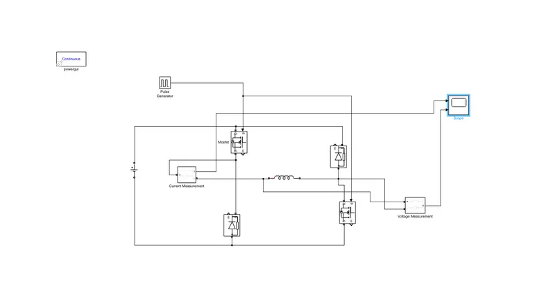
Blocks used:
-Mosfet
-diode
-scope
-inductor(load)
-pulse generator
-dc supply
-voltage and current measurement.
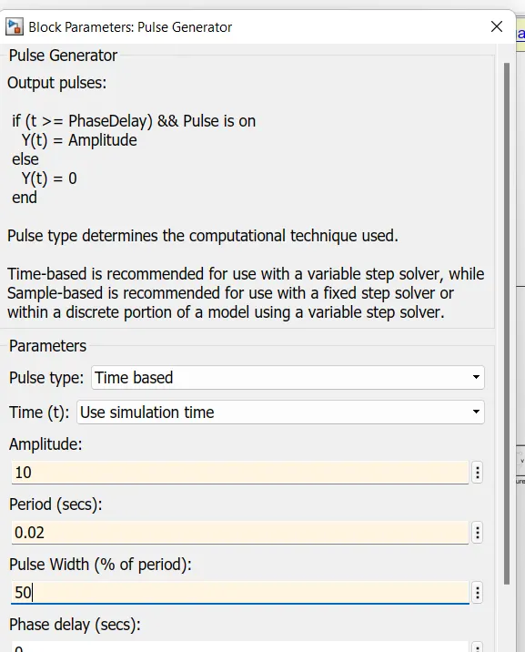
We will change pulse generation:
Output:-
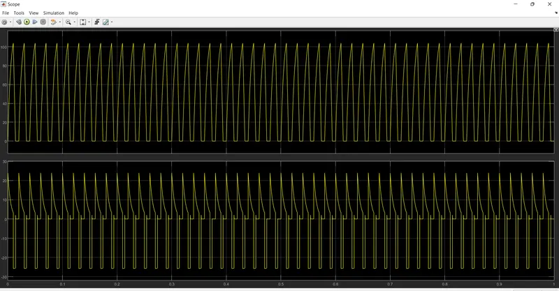
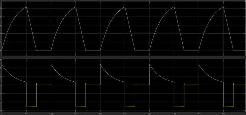
-We can zoom in and observe that in voltage waveform voltage is positive at some point and goes negative as well and remains in same form.
-In the current it is positive after remains constant to low inductance chosen but current is mostly positive due to low inductance chosen.
-This shows the two quadrant operation of a chopper type -D the current is positive and voltage can be positive and negative
Conclusion:- Thus created the chopper
Q3. Explain in a brief about operation of BLDC motor.
Ans:-
BLDC- Brushless DC motor
-It is operated without any brushess.
-These are electrically commuted (transistor switches) with power with switches insted of brushes.
-Due to use of brushes fault occurs and decreases efficiency of motor.
-To overcome disadvantage of brushsess BLDC motor is used.
-It works smoothly and increases efficiency.
Construction:
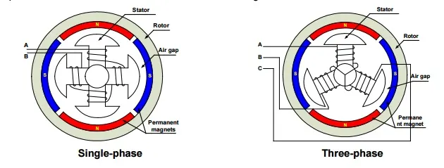
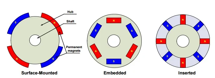
- BLDC motor also has stator,rotor and permanant magnet.
-Depend upon the stator there are single,two,three-phase are used mostly three-phase.
-Three-phase are commonly used.
-The rotor has permanent magnets to form two magnetic pole pairs, and surrounds the stator, which has the windings.
-A three phase BLDC motor has three windings each phase turns make the rotor revolve.
-Rotor is permanant magnet and stator is winding.