Week -2
SIMULINK MODEL OF DOORBELL
AIM: To make Simulink model of doorbell using solenoid block.
NTRODUCTION :
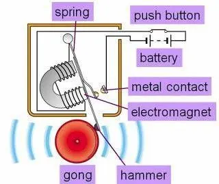
The diagram of doorbell is given below we can analyse the functioning mechanism of doorbell the electric doorbell consists of battery supply, the switch, the metal rod wounded with metallic wire we are using solenoid in this project the bell for tunning and the hammer for making noise.
METHADOLOGY:
Blocks required for Simulink model:
1)Scope
2)Pulse generator
3) Switch
4) Battery
5)Electrical reference
6) Solenoid
7)Ideal translational motion sensor
8)Mechanical translational reference
9)P-S to Simulink converter
After arranging the blocks will get the following diagram:
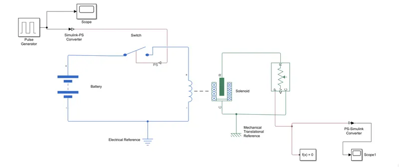
Doorbell is an example of a self-interrupting electrical circuit. Pushing the bell button closes the switch and connects the electromagnetic coil to the battery. The activated electromagnet then attracts the hammer, which hits the bell but also interrupts the electric circuit at the contact. When the doorbell button is pressed, the electrical circuits closes and results in the generation of an electromagnetic field. The magnetic field attracts the iron hammer, which pulls the contact arm away from the metal contact. The moving away of the contact arm breaks the circuit and thus turns off the electromagnet.
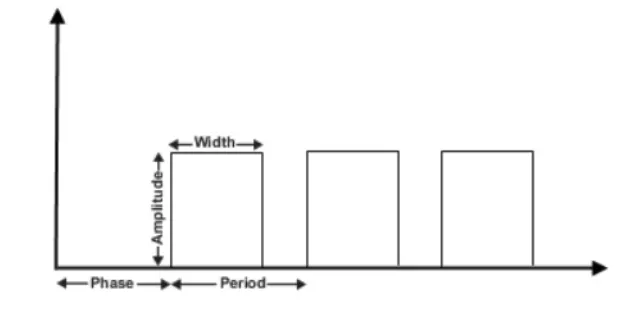
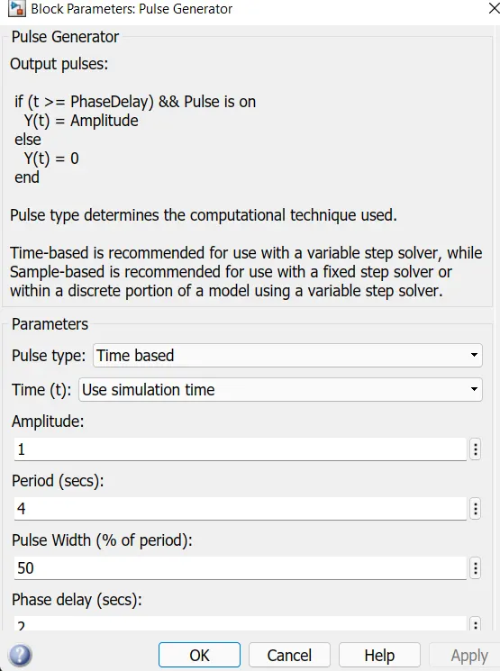
-As per the given situation we need to give 2 sec interval of time to open and close the circuit. Therefore we will use the pulse generator to create square waves, we can see the different parameters such as amplitude, width, time period.
-The switch is connected to the physical signal it opens and closes depend upon the value of external physical signal:
Greater value switch-close
Less value than switch-open
-After completing the battery switch, electrical reference block and the solenoid the circuit gets completed. Solenoid is basically an electric coil with a moveable core in the centre that is made from a ferromagnetic material. The core is often referred to as plunger.
- When current flows through the coil, a magnetic field is created around the coil. The strength of this field depends on the current, the number of windings and the material of the core.
-As a result of the magnetic field, the solenoid core is pulled towards the centre of the coil. As long as current is flowing, the core remains pulled towards the centre.
- As soon as the flow of current stops, the magnetic field disappears and the core is pushed down by a spring to its initial position.
-Now in the second part of the circuit c port of the solenoid is connected to the mechanical reference of the and the R port of solenoid is connected to the ideal translational motion sensor and this is connected to scope to get the output value of movement of solenoid.
After the results we’ll get following output:
1)pulse generator
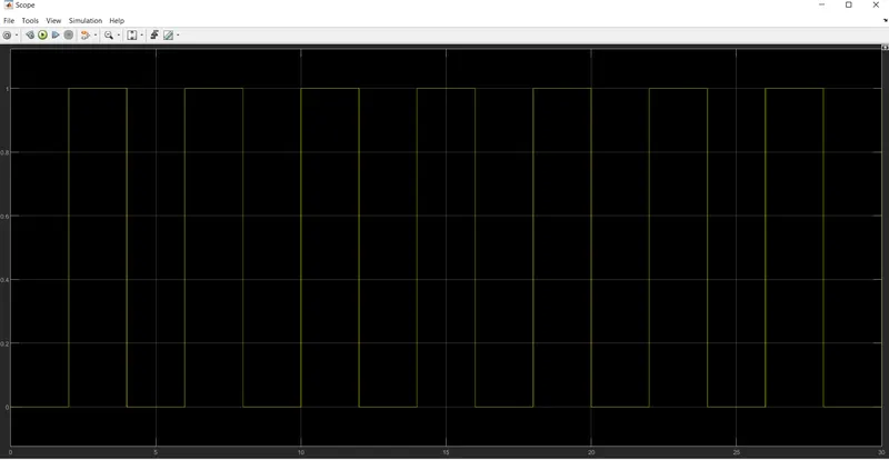
2)Output at scope

CONCLUSION:
The given time delay of 2sec the circuit opens and closes itself through switch when switch is closed the solenoid starts its action electricity passes through it due electromagnetism the hammer hits the bell and bell produces sound. We can see the sound produced by the bell in distorted time delay of 2 sec in the output graph.
THERMISTOR
AIM:
To sense the temperature of a heater and turn on turn off the fan as per the below condition:
- Temperature source: 20 degrees Celsius from 0 to 10 sec, 27 degree Celsius from 10 to 30 sec, 23 degree Celsius 30 to 50 sec.
- Fan condition- ON if the temperature above 25 degrees Celsius, OFF otherwise.
INTRODUCTION:
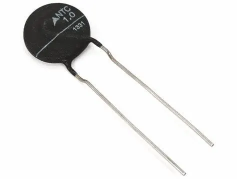
A thermistor is defined as a type of resistor whose electrical resistance varies with changes in temperature. Although all resistors’ resistance will fluctuate slightly with temperature, a thermistor is particularly sensitive to temperature changes. Thermistors act as a passive component in a circuit. Increase in voltage current indicates increase temperature.
BLOCKS USED IN SYSTEM:
- Voltage source
- Voltage sensor
- Resistor
- Thermistor
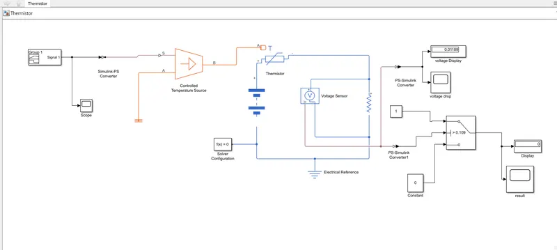
- Controlled temperature source
- Electrical reference
Signal building block is added to the input the values as per the given condition.
At point 1 time= 0 sec to 10 sec & temperature = 293k
At point 2 time = 10 sec to 30 sec & temperature = 300k
At point 3 time = 30 sec to 50 sec& temperature= 296k
RESULTS:
0 in the graph indicates fan is off.
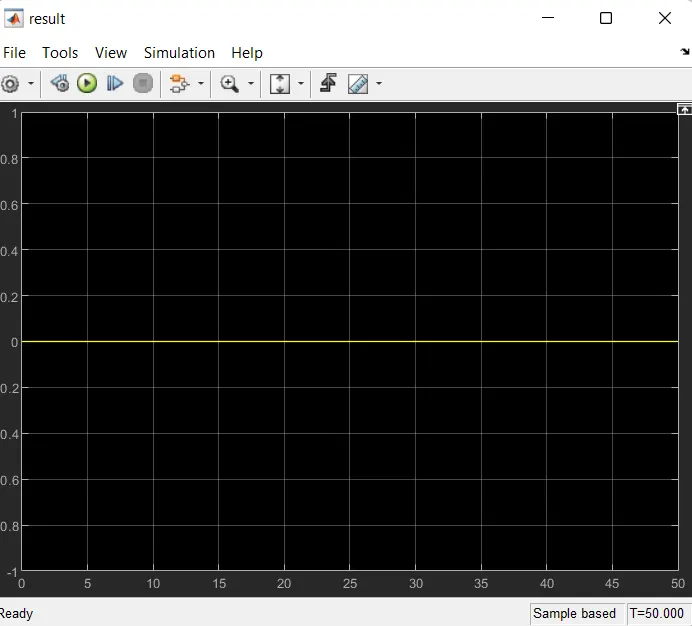
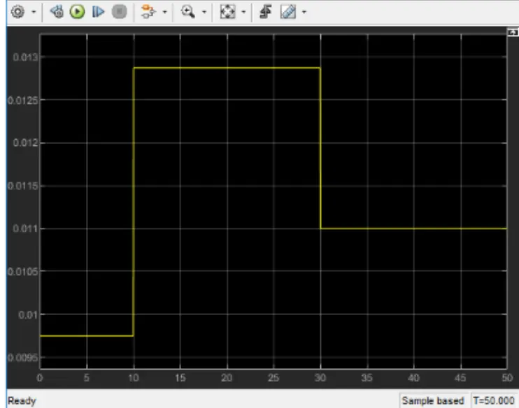
From 0 t0 10 fan is OFF because temperature is 293k which is below 298k, after 10 seconds which goes to 300k, so fan will turn ON because temperature is exceeding 298k after 30 sec the it goes to 296k which is less than 298k