Week - 4
AIM: To implement control logic of washing machine using state flow.
Objective:
1) Implement control logic of a washing machine using stateflow.
2) If the power supply is available, system will be active.
3) If the water supply is not available, stop the process and indicate through LED.
4)Soaking time should be 200 sec followed by washing machine time 100 sec.
5) Then rinsing happens for next 20 sec & dryer runs for 50 sec.
Methodology:
Stateflow provides a graphical language that includes state transition diagrams, flow charts, state transition tables, and truth tables. You can use Stateflow to describe how MATLAB algorithms and Simulink® models react to input signals, events, and time-based conditions. Stateflow enables you to design and develop supervisory control, task scheduling, fault management, communication protocols, user interfaces, and hybrid systems.With Stateflow, you model combinatorial and sequential decision logic that can be simulated as a block within a Simulink model or executed as an object in MATLAB. Graphical animation enables you to analyze and debug your logic while it is executing. Edit-time and run-time checks ensure design consistency and completeness before implementation.
BLOCKS USED:
1)Constant block
2)Switch block
3)Lamp block
4)Chart block
5)Display block
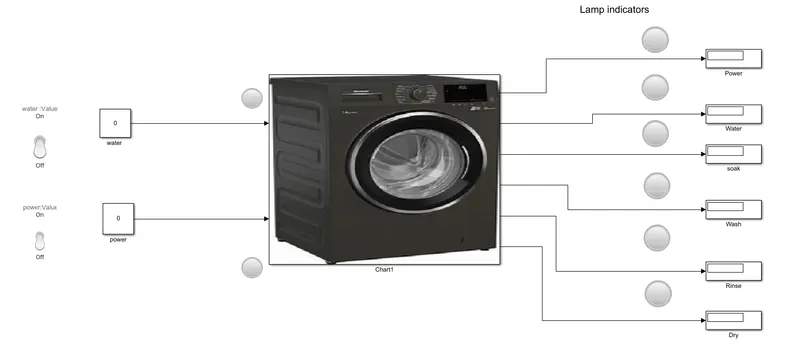
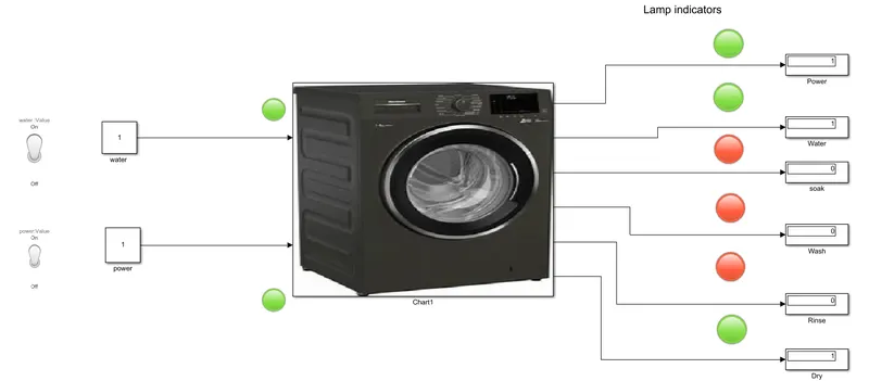
Constant blocks are used for the putting input power and water supply. Switch block for determining output, lamp is used for indicating running signal, chart block is used for creating control logic program, display for display output.
Washing machine principle:
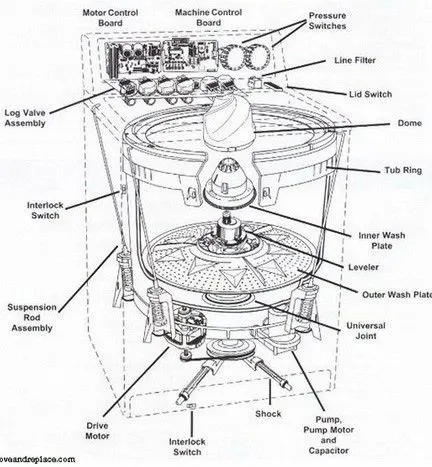
The main principles behind the working of a washing machine are the centrifugal and centripetal forces, where centrifugation helps quicken the process of sedimentation of different density particles to clean the laundry in the washing machine.
The washing machine operates in two primary cycles. These are the wash cycle and the rinse cycle.
The wash cycle involves the principle of centrifugal force. This force’s direction is from inside to outside, which makes sure that every part of the cloth is rinsed adequately in the soap water mixed in the machine.
The rinse cycle involves the principle of centripetal force. This force acts from outside to inside and creates a vacuum-like space in the middle of the washing machine.
These two cycles work one after another several time, and as a result, the entire cleaning process occurs.
SIMULINK MODEL:
STATEFLOW CHART:
STATEFLOW EXPLANATION:
The stateflow works as follows:
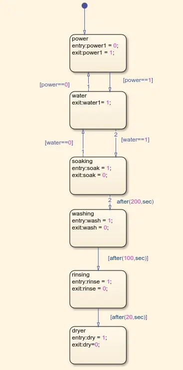
1)The first step is Power the program checks weather the power is ON/OFF and proceed to the next step if the power is ON then it will go to next step or else it will not go further. We have defined power1(variable) exit: power1 means ON (1) power will pass to next step and if the power1=0 means OFF it will not pass on next state.
2)The next step is water it will work same as per the power if the water is ON then it will go to next step or else it will not go further. We have defined water1(variable) exit: water1 means ON (1) water will pass to next step and if the water1=0 means OFF it will not pass on next state.
3)The next step is soak state once the water is filled cloths will soak the water if the soak is ON then it will go to next step or else it will not go further. We have defined soak(variable) exit: soak means ON (1) soak state will pass to next step and if the soak state=0 means OFF it will not pass on next state.
4)The next step is wash state where cloths are washed after the mentioned condition(between soaking and washing) after 200sec the soaking washing takes place.
5)After washing state the risen state it will take place after 100 sec of washing.
6)The next step is dry state where cloths dry inside the machine it will happen after given condition.
This is about machine we have defined the variable entered as output variable and power and water as inputs the slider switches are used for input power and water and connected to chart.
Slider switch is OFF= 0 there is water / power supply.
And the outputs are connected to the displays and are connected to lamp blocks if the it will turn green if the state is going.
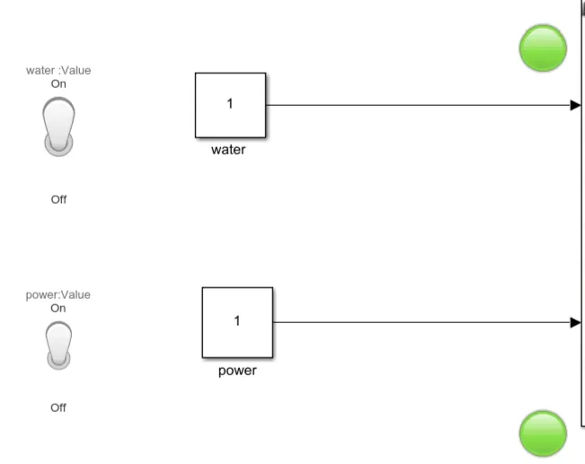
Condition 1- Both water and power supply
Water and power are supplied
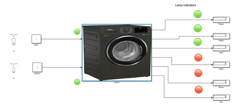
Condition 2-Soaking state
Will continued till 200sec
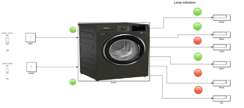
Washing state-
After 200 sec washing state will start and being continued till 300 sec.
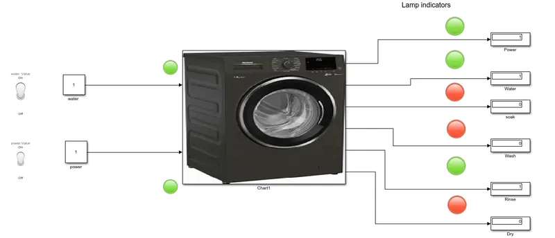
Rinsing state:
After 300 sec rinsing starts
Drying state:
After 320 sec drying initiated and continued till 370 sec and once the rinsing state is crossed the water supply is cut off.
Conclusion: - Hence all objectives achieved.
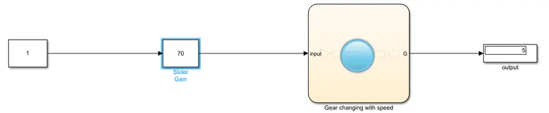
- Make a Simulink chart for the “Gear shift” logic as per below conditions:
Speed Range(kmph) Gear
0 to 15 1
16 to 25 2
26 to 40 3
41 to 60 4
Above 61 5
Give speed input while the simulation is running & display the gear number.
GEAR SHIFT USING STATE- FLOW:
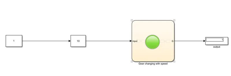
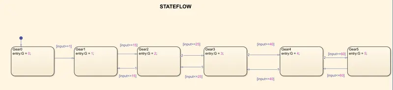
Case 1- At 10 kmph the gear shifts from neutral to first gear.
Case 2- At 20 kmph the gear shifts from first gear to second gear
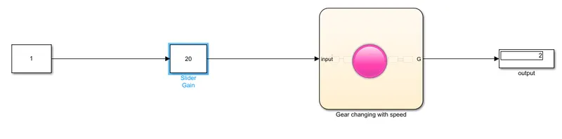
Case 3- At 30 kmph the gear shifts from first gear to third gear
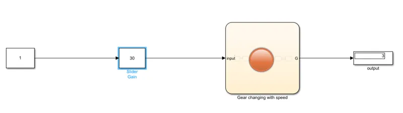
Case 4- At 50 kmph the gear shifts from first gear to forth gear
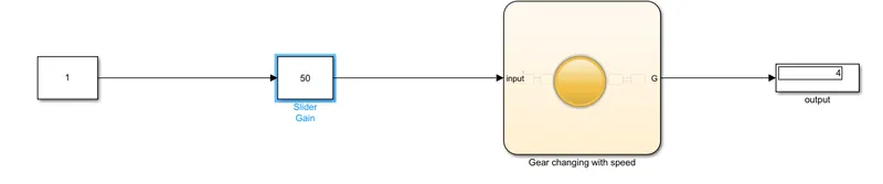
Case 5- At 70 kmph the gear shifts from first gear to fifth gear