Project-1: Powertrain for aircraft in runways
Part A:
Q1. Search and list out the total weight of various types of aircrafts.
Ans:-
The maximum allowable weight for an aircraft is determined by design considerations. The manufacturer provides the aircraft operator with the empty weight of the aircraft and the location of its empty weight center of gravity (EWCG) at the time the certified aircraft leaves the factory.
However, the maximum operational weight may be less than the maximum allowable weight due to such considerations as high-density altitude or high-drag field conditions caused by wet grass or water on the runway. The maximum operational weight may also be limited by the departure or arrival airport’s runway length.
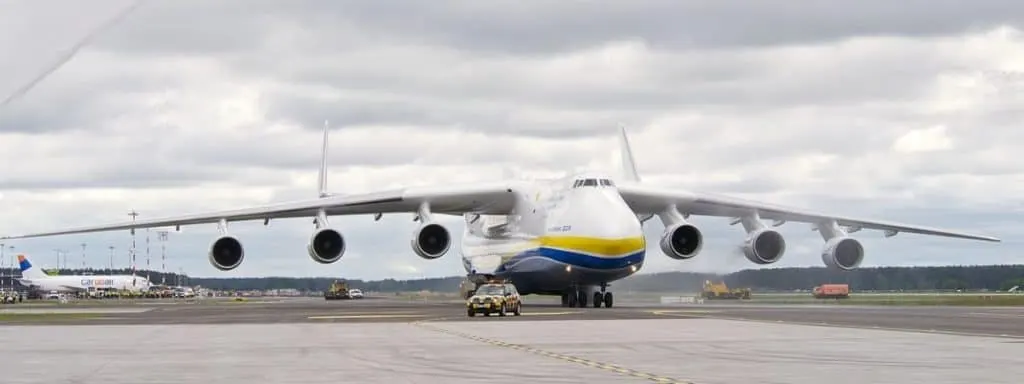
Typical Airplane Weights:
| Aircraft | Empty Weight | Max Fuel Weight | Max Cargo Weight | Max Gross Takeoff Weight |
|---|---|---|---|---|
| Antanov AN-225 | 628,000 lbs 285,000 kg |
661,400 lbs 300,000 kg |
417,000 lbs 190,000 kg |
1,411,000 lbs 640,000 kg |
| Airbus A380-800 | 611,000 lbs 277,000 kg |
560,000 lbs 254,000 kg |
185,000 lbs 84,000 kg |
1,268,000 lbs 575,000 kg |
| Boeing 747-800 | 485,300 lbs 220,100 kg |
427,400 lbs 194,000 kg |
295,000 lbs 134,000 kg |
987,000 lbs 447,700 kg |
| Airbus A340-500 | 370,000 lbs 168,000 kg |
386,300 lbs 175,000 kg |
119,000 lbs 54,000 kg |
820,000 lbs 372,000 kg |
| Boeing 777-300ER | 370,000 lbs 168,000 kg | 320,800 lbs 145,500 kg | 148,000 lbs 67,100 kg |
776,000 lbs 352,000 kg |
| Boeing 787-10 | 299,000 lbs 135,500 kg | 223,500 lbs 101,500 kg |
126,300 lbs 57,300 kg | 560,000 lbs 254,000 kg |
| Boeing 737-900 | 98,500 lbs 44,700 kg |
53,100 lbs 24,000 kg |
44,600 lbs 20,200 kg |
187,000 lbs 85,000 kg |
| Airbus A320-100 | 93,900 lbs 42,600 kg |
48,700 lbs 22,100 kg |
44,000 lbs 20,000 kg |
150,000 lbs 68,000 kg |
| Embraer 190 | 63,500 lbs 28,800 kg |
28,600 lbs 13,000 kg |
28,800 lbs 13,100 kg |
106,000 lbs 48,000 kg |
| Gulfstream G650 | 54,000 lbs 24,500 kg | 48,200 lbs 21,900 kg | 6,500 lbs 3,000 kg |
100,000 lbs 45,200 kg |
| Bombardier CRJ900 | 48,160 lbs 21,850 kg | 19,600 lbs 8,900 kg | 6,075 lbs 2,760 kg | 80,500 lbs 36,500 kg |
| Bombardier Q400 | 39,300 lbs 17,800 kg |
11,700 lbs 5,300 kg |
18,700 lbs 8,500 kg |
62,000 lbs 28,000 kg |
|
Learjet 75 |
13,900 lbs 6,300 kg | 6,060 lbs 2,750 kg |
2,900 lbs 1,300 kg |
21,500 lbs 9,700 kg |
| Cessna Citation CJ4 | 10,300 lbs 4,700 kg | 5,800 lbs 2,650 kg |
2,200 lbs 1,000 kg | 17,200 lbs 7,800 kg |
| Beechcraft King Air B100 | 7,100 lbs 3,200 kg | 3,200 lbs 1,450 kg |
4,150 lbs 1,900 kg |
12,000 lbs 5,400 kg |
| Diamond DA50 RG | 3,200 lbs 1,450 kg |
340 lbs 155 lbs |
1,250 lbs 560 kg |
4,400 lbs 2,000 kg |
| Beechcraft Bonaza G36 | 2,500 lbs 1,150 kg | 450 lbs 200 kg |
850 lbs 385 kg |
3,660 lbs 1,660 kg |
| Cessna 206H | 2,200 lbs 990 kg |
520 lbs 235 kg |
1,150 lbs 520 kg |
3,600 lbs 1,630 kg |
| Sirrus SR22 | 2,250 lbs 1,000 kg | 485 lbs 220 kg |
950 lbs 430 kg |
3,600 lbs 1,630 kg |
| Cessna 172R | 1,700 lbs 770 kg |
380 lbs 170 kg |
560 lbs 255 kg |
2,425 lbs 1,100 kg |
Q2. Is there any difference between ground speed and air speed?
Ans:-
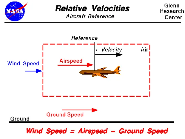
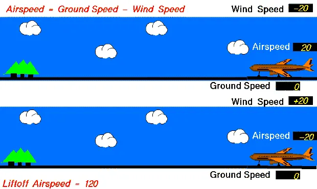
Airspeed:
Airspeed is the speed at which an aircraft is moving relative to the air it is flying in. As such, it’s also the speed at which the air is flowing around the aircraft’s wings.Basically it is the speed relative to the air it is flying in. Airspeed is what determines whether there is enough airflow around an aircraft to make it fly or not.
Ground speed:
Ground speed is the aircraft’s speed relative to the ground ground speed is the airplane's speed relative to the surface of the earth Ground speed is what determines how fast an aircraft will go to its destination. Basically ground speed is a term used in aviation when referring to the velocity of an aircraft, specifically how fast an aircraft is traveling in relationship to the ground.
Q3. Why is it not recommended to use aircraft engine power to move it on the ground at Airport?
Ans:-
For movement on the ground the aircraft uses it own engine power, which is called taxing.
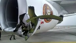
Although many aircrafts are capable of moving in backward using reverese thrust, as result the jet blast or pop wash might cause damage to the terminal building or equipment.
Aircraft doesn't have a reverse gear. It uses reverse thrust to move backward. Reverse thrust is nothing but reversing the direction of the thrust that comes out from aircraft engines. In reverse thrust engines suck air from the back and release the thrust from the front side.
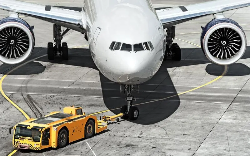
In the aircrafts engine, is close to ground may also blow sand and debris forward and then suck them into the engine, causing damage to the engine. Therefore there are pushback trucks ot tugs are used in the airport.
A pushback tractors or tugs lifts the front wheel of the aircraft, their role in most airports is to move the aircraft away from the parking spot on to the taxiways, which is called towing.
-Due to high power engine running it may cause damage to the aircraft itself, other aircraft nearby or to structures of airstrip.
-There is a risk of injury to ground support personal who may be in relatively close proximity to the aircraft.
- It is easier for truck driver to see the surroundings better than the pilot sitting in the cockpit with limited window. The pushback driver knows the airport better than the pilot.
4. How an aircraft is pushed to runway when its ready to take off?
Ans:-

-Aircraft doesn't have a reverse gear. It uses reverse thrust to move backward. Reverse thrust is nothing but reversing the direction of the thrust that comes out from aircraft engines. In reverse thrust engines suck air from the back and release the thrust from the front side.
- pushback truck reverses the aircraft into taxiing position, pushing it with a towbar attached to the nose-wheel strut. Or, in the most modern versions, by actually lifting the wheel. That speeds up coupling and decoupling.
The aircraft taxis to the runway to depart at the agreed time. Once the pushback is completed, the towbar is disconnected, and any bypass pin is removed.
-The pilot waits for permission to take off from air-traffic control. This is possible once the departure route is clear. As soon as the go-ahead is received, the plane takes to the air at full power.
Q5. Learn about take off power, tyre design, rolling resistance, tyre pressure, brake forces when landing.
Ans:-
For light aircraft, usually full power is used during takeoff. Large transport category (airliner) aircraft may use a reduced power for takeoff, where less than full power is applied in order to prolong engine life, reduce maintenance costs and reduce noise emissions. In some emergency cases, the power used can then be increased to increase the aircraft's performance. Before takeoff, the engines, particularly piston engines, are routinely run up at high power to check for engine-related problems.
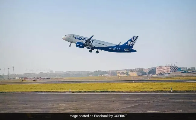
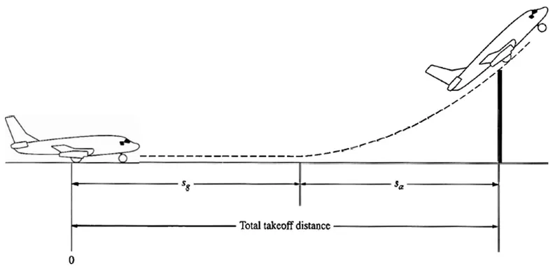
An airplane is motionless at the end of a runway. This is denoted by location O. The pilot releases the brakes and pushes the throttle to maximum takeoff power, and the airplane accelerates down the runway. At some distance from its starting point, the airplane lifts into the air. The distance the airplane cover along the runway before it lifts into the air is called the ground roll (sg). The total takeoff distance also includes the extra distance covered over the ground after the airplane is airborne but before it clears an obstacle of 50 ft for military aircraft and 35 ft for commercial aircraft. This is denoted by sa. The sum of sg and sa is the total takeoff distance.
Tyre design:
Requirements for aircraft tyre :
- They should support the weight of an aircraft while it is on the ground.
- It should also provide the necessary traction for braking and stopping of an aeroplane.
- Tyre also helps to absorb the shock of landing and provide cushioning the roughness of takeoff, roll-out, and taxi operations.
Aircraft tyres, tubeless or tube type, provide a cushion of air that helps absorb the shocks and roughness of landings and takeoffs they support the weight of the aircraft while on the ground and provide the necessary traction for braking and stopping aircraft on landing. Thus, aircraft tyres must be carefully maintained to meet the rigorous demands of their basic job to accept a variety of static and dynamic stresses dependably in a wide range of operating conditions.
Dissect an aircraft tyre and you'll find that it's one of the strongest and toughest pneumatic tyres made. It must withstand high speeds and very heavy static and dynamic loads. For example, the main gear tyres of a four-engine jet transport are required to withstand landing speeds up to 250 mph, as well as static and dynamic loads as high as 22 and 33 tons respectively.
Automobile tyres are pressurized to around 30-40 psi. If large aircraft tyres were filled with 35 psi the large aircraft tyre pressures are very high. A Boeing 767-300 main wheel is inflated to 205 psi.
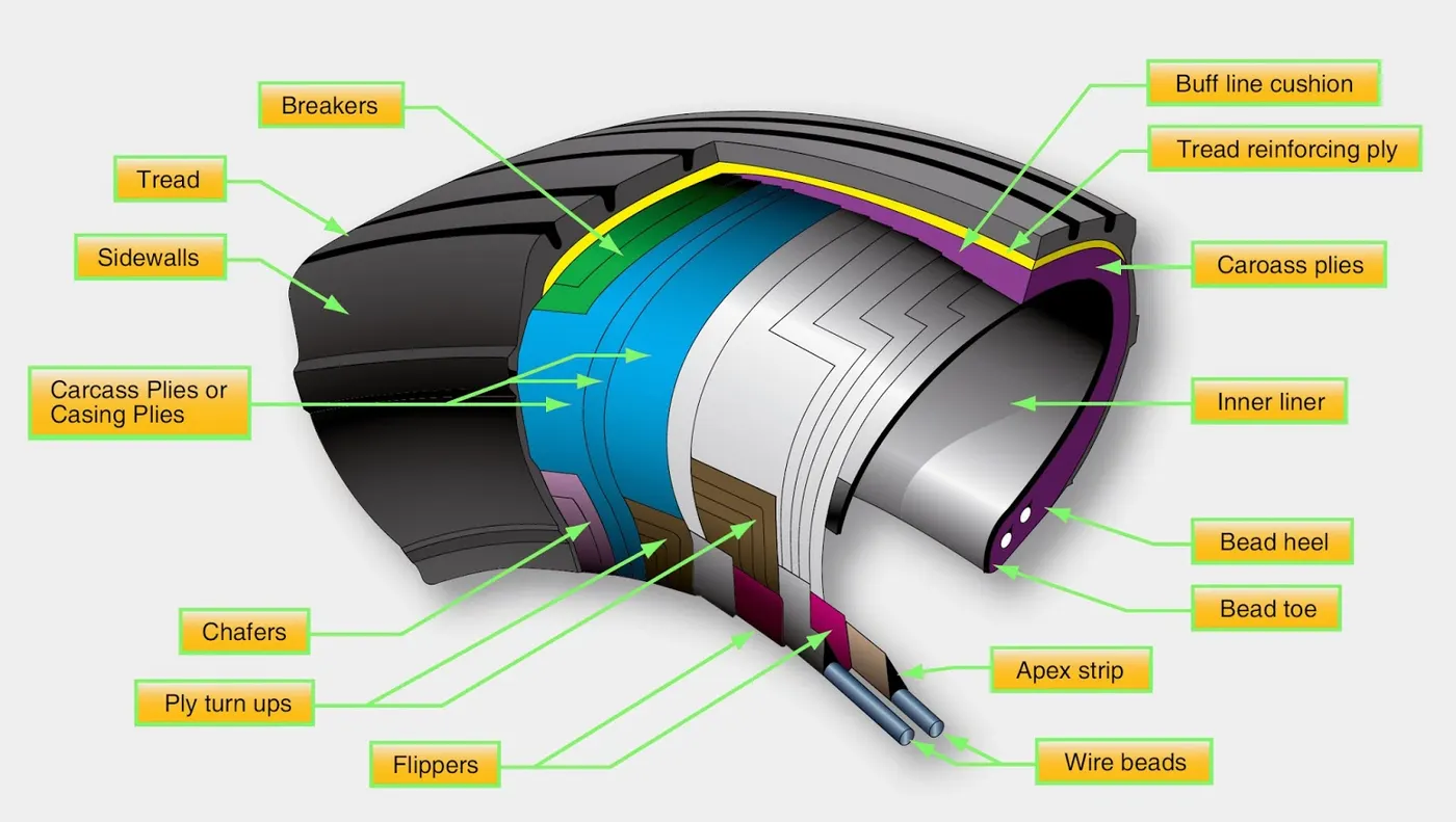
Tread: The tread is made of rubber mixed with other additives to obtain the desired level of toughness, durability, and resistance to wear. The tread pattern is designed to aircraft operational requirements, with the ribbed tread design used widely due to its good traction under varying runway conditions.
Sidewall: The sidewall is a protective layer of rubber that covers the outer casing ply. It extends from the tread edge to the bead area.
Tread Reinforcing Ply: One or more layers of fabric that strengthens and stabilizes the tread area for high-speed operation. It also serves as a reference for the buffing process when tires are retreaded.
Buff Line Cushion: The buff line cushion is made of rubber compound to enhance the adhesion between the tread reinforcing ply and the breakers or casing plies. It is of sufficient thickness to allow for the removal of the old tread when the tire is retreaded.
Breakers: Breakers are reinforcing plies of rubber-coated fabric placed under the buff line cushion to protect casing plies and strengthen and stabilize the tread area. They are considered an integral part of the casing construction.
Casing Plies: Alternate layers of rubber-coated fabric (running at opposite angles to one another) provide the strength of the tire.
Wire Beads: Hoops of high tensile strength steel wire that anchor the casing plies and provide a firm mounting surface on the wheel. The outer edge of the bead that fits against the wheel flange is called the bead heel. The inner bead edge is called the bead toe.
Apex Strip: A wedge of rubber affixed to the top of the bead bundle.
Bead toe: It is the inner edge of the bead.
Bead heel: It is the outer edge of the heel.
Flippers: Layers of rubberized fabric that help anchor the bead wires to the casing and improve the durability of the tire.
Ply Turnups: The casing plies are anchored by wrapping them around the wire beads, thus forming the ply turnups.
Chafer: A protective layer of rubber and/or fabric located between the casing plies and wheel to minimize chafing.
Liner: In tubeless tires, the liner is a layer of low permeability rubber that acts as a built-in tube and restricts gas from diffusing into the casing plies. In tube-type tires, a thinner liner is used to prevent tube chafing against the inside ply.
Caroass Plies: Layers of rubber-coated fabric piles which have the cords running from bead to bead. These provide the tire with strength in the sidewall area.
Tubeless tyres are more advantageous over tube-type. There is no longer the use of tube-type tyre in recent aviation. Nowadays all airliners are using tubeless tyres. Tubeless that are meant to be used without a tube has the word TUBELESS on the sidewall of the tyre.
Aircraft tyres must have an approved speed and load rating and have sufficient clearance when retracted through landing gear to allow for tyre growth. Tyre growth is the increase in the size of the tyre due to centrifugal forces at high speed.
Retreading – Retreading is methods of restoring a worn tyre by renewing the tread area or by renewing the tread area plus one or both sidewalls. Repairs are included in the tyre retreading process.
Load Rating – Load rating is the maximum permissible load at a specified inflation pressure.
Ply Rating – Ply Rating is used to identify the maximum recommended load rating and inflation pressure for a specified tyre. It is an index of tyre strength.
Speed Rating – The speed rating is the maximum takeoff speed to which the tyre has been tested.
Skid Depth – Skid depth is the distance between the tread surface and the deepest groove as measured in the mould.
All commercial aircraft tyres approved under FAA Requirement Technical Standard Order (TSO) C62. A TSO is a minimum performance standard for specified materials, parts, and appliances used on civil aircraft.
Rolling resistance:
μrr">μ= Rolling resistance coefficent
m = Total mass of the aircraft in kg
g = Gravitational constant i.e, 9.8 m/s2">s2
The value varies with speed. Tire pressure increases,its value decreases.
Tyre pressure:
An aircraft tire or tyre is designed to withstand extremely heavy loads for short durations.The number of tires required for aircraft increases with the weight of the aircraft, as the weight of the airplane needs to be distributed more evenly. Aircraft tire tread patterns are designed to facilitate stability in high crosswind conditions, to channel water away to prevent hydroplaning, and for braking effect.
Aircraft tires also include fusible plugs (which are assembled on the inside of the wheels), designed to melt at a certain temperature. Tires often overheat if maximum braking is applied during an aborted takeoff or an emergency landing. The fuses provide a safer failure mode that prevents tire explosions by deflating in a controlled manner, thus minimizing damage to aircraft and objects in the surrounding environment.
Automobile tyres are pressurized to around 30-40 psi. If large aircraft tyres were filled with 35 psi the large aircraft tyre pressures are very high. A Boeing 767-300 main wheel is inflated to 205 psi.
Brake forces when landing:
Aircraft brakes stop a moving aircraft by converting its kinetic energy to heat energy by means of friction between rotating and stationary discs located in brake assemblies in the wheels.
Brakes provide this critical stopping function during landings to enable airplanes to stop within the length of the runway. They also stop aircraft during rejected takeoff events, in which an attempted takeoff is canceled as the airplane is rolling down the runway before it lifts off from the ground due to engine failure, tire blowout, other system failure or direction from air traffic control.
The most common type of brake used on aircraft is the disc brake. Disc brakes function by exploiting friction between rotating and stationary discs inside the brake.
Types of brake systems used in plane:
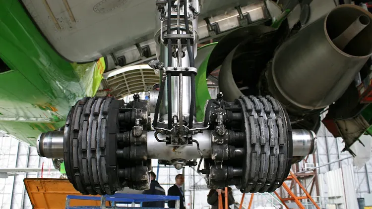
Wheel brakes:- Carbon disc brakes used for wheel brakes. This is the brakes used for final stop of aircraft during landing, taxing, during all ground requirements. Further this brakes used for wheel braking after takeoff to remove any gyro effect on aircraft or landing gear.
Wing spoilers:- spoiler used as air brakes. During cruise and approach, spoiler surface used for reducing speed wing raised wing spoilers create the drag, which essentially slows down the airplane so that it’s able to brake more quickly.
Ground:- Same surface used as ground brakes during landing. During this phase, these surfaces deployed fully and spoil the lift during ground operation. Spoiling lift during landing and braking phase, ground spoiler (same surface) spoil the lift and makes wheel braking more effective.
Reverse thrust:- Reverse thrust used in conjunction with ground spoiler to reduce forward thrust or speed. Engine forward thrust reversed towards backward side with the help of Reverse thrust.
Parachute:- parachute used for braking in military aircrafts or fighter aircrafts.
Part B:
6. A. With necessary assumptions, calculate the force and power required to push / pull an aircraft by a towing vehicle.
Ans:-
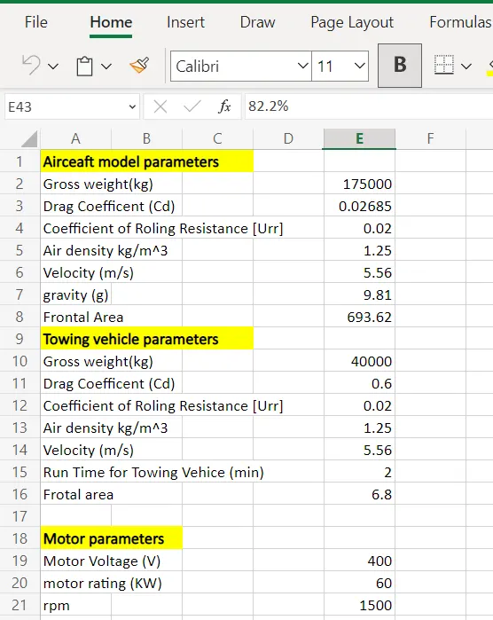
We will calculate the force and power required to push and pull an aircraft by towing vehicle
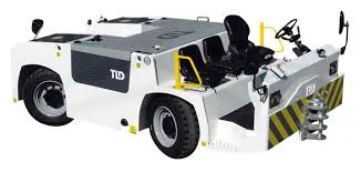
The TMX-550 is an Aircraft Towing Tractor, gross weight ranging from 121,250 lbs. (55,000 kg.) to 132,270 lbs. (60,000 kg.), with a maximum driveline capability of 40,100 daN (88,400 lbs.). It is designed to perform push back and towing operations on medium and wide body aircraft such as:
- Boeing B767, B777, B747, B787
- Airbus A300, A310, A330, A340, A350, A380.
Formula used:
Total Force = F r r + F a d
Rolling resistance Force Frr = μ.m.g
Drag Force (Fad)=12.ρ.A.Cd.v2
Solution:
In the first step, we have to find out the rolling resistance force and air drag force for both towing vehicle and airbus to obtain the force and power value during the towing process,
To find rolling resistance force:
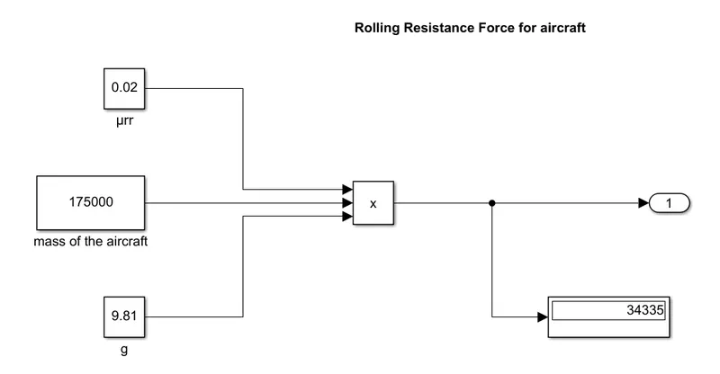
For Aircraft :
Rolling resistance force Frr = μ.m.g
Where,
μrr= Coefficient of rolling resistance of aircraft = 0.02
m1=massof the aircraft=175000kg
g = gravitational force = 9.8 ms2
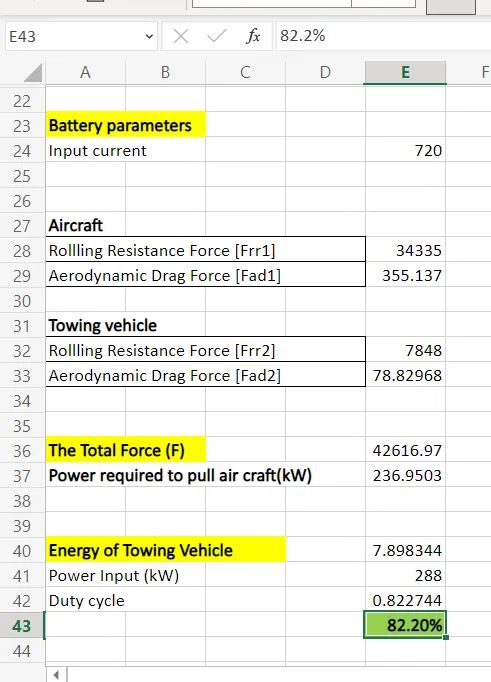
∴(Frr1)= 0.02 x 175000 x 9.81
= 34335 N
For Towing Vehicle:
Rolling resistance force (Frr2)=μrr.m2.g
Where,
μrr= Coefficient of rolling resistance of towing vehicle = 0.02
m2= mass of the towing vehicle = 40000 kg
g = gravitational force = 9.8 ms2
(Frr2) = 0.02 x 40000 x 9..81
= 7848 N
So, the Rolling resistance force (Frr)=Frr1+Frr2
= 34335 + 7848
= 42183N
To find Air drag force:
The Air Drag Force (Fad)=12.ρ.A.Cd.v2
Where,
ρ = Density of air
A = frontal area of the vehicle on which the air strikes
v = velocity of the vehicle
Cd = Drag Coefficient
For Aircraft :
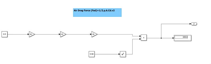
Air Drag Force (Fad)=1/2.ρ.A.Cd.v2
Where,
ρ = 1.25 kg/m3
A = Height of the airbus x Width of the airbus = 15.80 x 43.90 = 693.62 m2
Assume that vehicle running at the speed of 20 kmph.
v=(20x5/18)=5.56m/s
Cd = Drag Coefficient of aircraft = 0.02685
∴(Fad1)=1/2x1.25x693.62x0.0265x(5.56)2
= 355.137 N
For Towing Vehicle:
Air Drag Force (Fad2)=12.ρ.A2.Cd2.v2
Where,
ρ = 1.25 kg/m3
A2 = Height of the towing vehicle x Width of the towing vehicle = 2 x 3.4 = 6.8 m2
Assume that vehicle running at the speed of 20 kmph.
∴ v=(20x5/18)=5.56m/s
Cd2 = Drag Coefficient of the towing vehice = 0.6
∴(Fad2)=1/2x1.25x6.8x0.6x(5.56)2
= 78.82 N
So, the Air Drag Force (Fad)=(Fad1)+(Fad2)
= 355.137 + 78.82
= 437.13 N
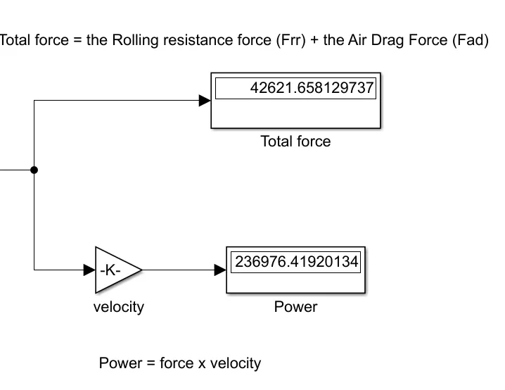
Now, the total force (F) = the Rolling resistance force (Frr) + the Air Drag Force (Fad)
= 42183 + 437.13
= 42620.13 N
Power required to push/pull the aircraft:
Power = Total Force x velocity
= 42620.13x 5.56
= 236967.756W
Therefore, Power = 236.96 kW
B. Develop the model for the calculated force and power using Simulink.
Ans:-
Simulink model:
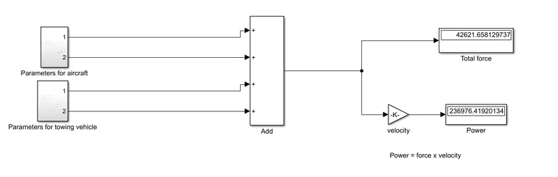
Aircraft Parameter measurement:
Towing vehicle Parameter measurement:
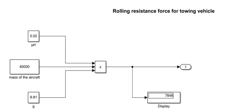
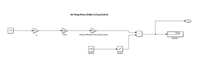
Total force and power calculation:
Q7). A. Design an electric powertrain with type of motor, it’s power rating, and energy requirement to fulfill aircraft towing application in Simulink. Estimate the duty cycle range to control the aircraft speed from zero to highest. Make all required assumptions. Prepare a table of assumed parameters. Draw a block diagram of the powertrain.
Ans:-
We have used the same parameters in both questions
we have to find out the energy required for the vehicle.
Standard or Higher Gross Weight = 175000 kg
Height = 15.80 m
Width = 43.90 m
Drag Coefficent (Cd) = 0.02685
mass of the towing vehicle = 40000 kg
Height = 2m
Tyre Size = 0.5715m
Maximum Governed Speed = 20 mph
time taken for towing vehicle = 2 minutes
Energy = Power x t
Where,
t = time taken for towing vehicle
Energy= 236.96 x 120 / 3600
= 7.89KWh
Now we will find the duty cycle
we know;
Power = Voltage x Current
we will consider the
Input Voltage supply = 400 V
Input Current Value = 720 A
Power input = 400 x 720 = 288000 W
Power input = 288kW