PWM Controlled Fan Load using DC motor
AIM: - To create a matlab/simulink model of PWM controlled fan load using DC motor
OBJECTIVE: -
-Use of controlled PWM and H-bridge circuit for controlling a DC motor with fan type load.
-Analysis of plots from results.
-Pulse width modulation reduces the average power delivered by an electrical signal by converting the signal into discrete parts. In the PWM technique, the signal’s energy is distributed through a series of pulses rather than a continuously varying (analog) signal.
-PWM signal stays ON for a given time and stays OFF for a certain time. The percentage of time for which the signal remains ON is known as the duty cycle. If the signal is always ON then the signal must have a 100 % duty cycle.
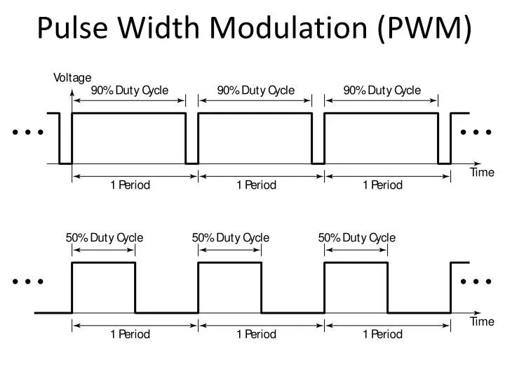
The formula to calculate the duty cycle is given as follows:
Duty Cycle = Turn ON time / Turn ON time + Turn OFF time
Frequency = 1 / Time period
Time period = ON time + OFF time
H-bridge circuit:
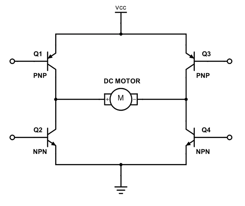
- H-bridge is an electronic circuit that switches the polarity of a voltage applied to a load.
-Current will flow from source (+ve) to load (–ve).
-Signal is given through gate terminals to switch ON the devices.
-Load is fitted which is DC motor between four switches which shapes like H.
-We cannot trigger the Q1 and Q2 together to avoid short circuit also we can’t connect Q3 and 4 together which can create low resistance path.
- Only one switch from both sides should be triggered ON two quadrant operation of DC motor.
-When Q1 and Q4 are triggered, motor will rotate in forward direction.
-When Q2 and Q3 are triggered, motor will rotate in reverse direction.
Load characteristics:
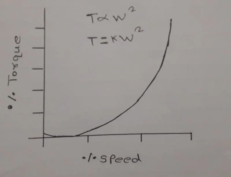
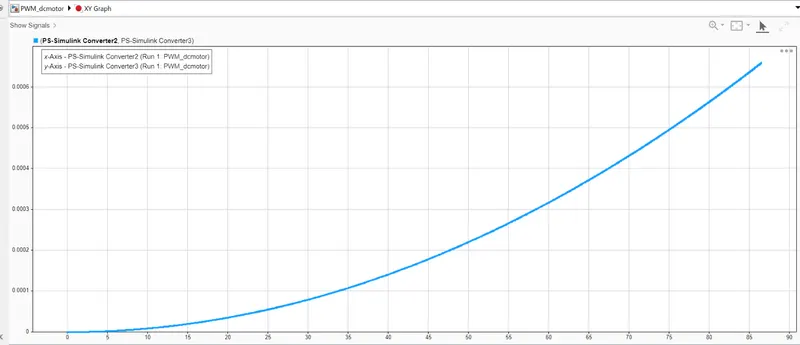
The torque speed curve of a load is a plot showing its torque requirement on the y-axis versus the speed on the x-axis. It’s the torque requirement of the load from zero speed to full speed.
The torque at the load will be proportional to square of the speed.
Block Diagram:
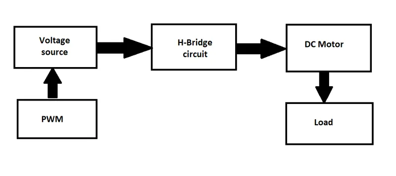
BLOCKS USED: -
-Controlled PWM voltage
-Pulse generator
-From and Goto blocks
-H bridge
-DC Motor
-Voltage and current sensor
-Ideal rotational motion sensor
-Aerodynamic drag
-Square law (for torque speed relation)
-X Y graph (for speed vs torque)
Simulink model: -
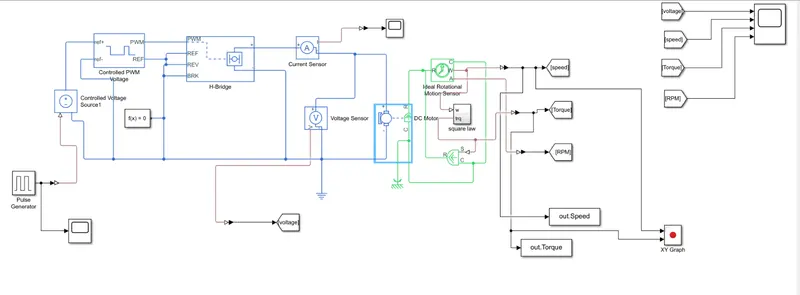
-Run time is 50
Result:
Scope result of pulse generator:
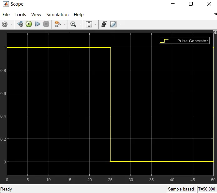
-Shows that half time on and half time OFF we have given period of 50%
-X-Y graph which shows relation between torque and speed as per the load characteristics:
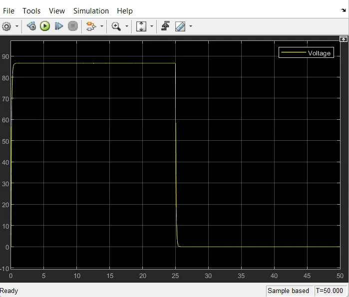
Output of the scope blocks of Voltage,speed,RPM and torque:
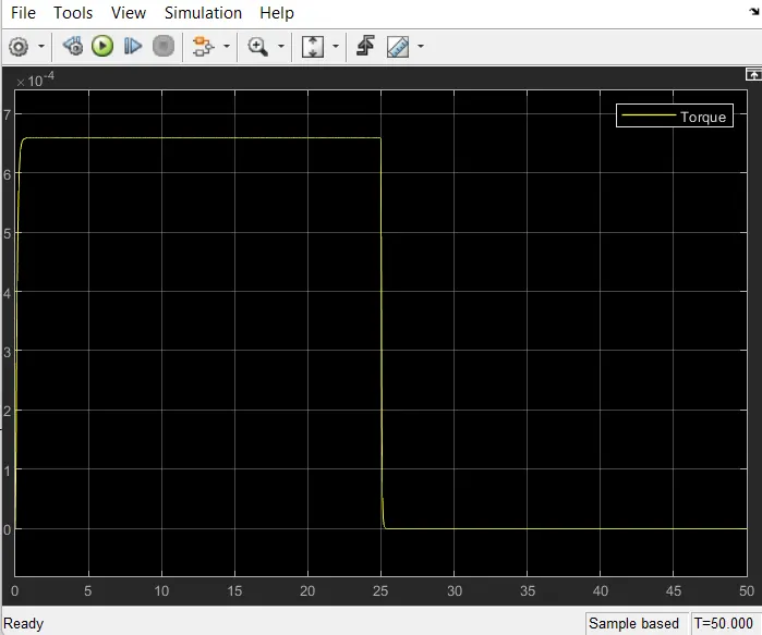
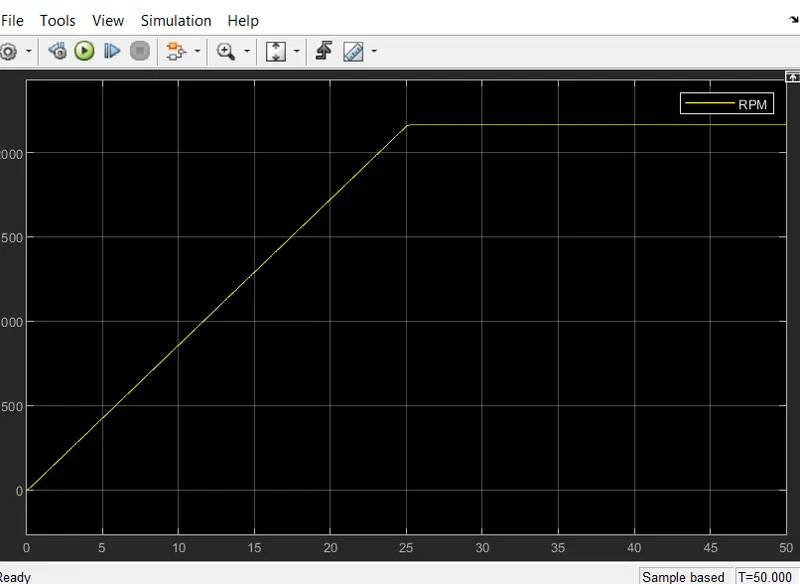
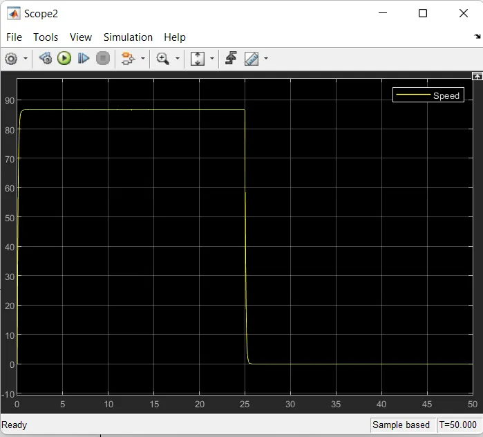
Conclusion:-
A PWM controlled DC motor using an H bridge circuit was modelled in Simulink and results were analyzed. The output plots justified the theory discussed. The load torque characteristics of a fan is obtained. The full speed was observed for a full voltage of 12V from DC motor.