Project
AIM:
To study and analyze The BAJA All-Terrain Vehicle (ATV) using Simulink and compare between different models.
OBJECTIVES: -
1.Prepare a technical report explaining the functions of the subsystems & blocks used for preparing the model.
2.To explain difference between all the five models provided.
- Study and comment on the result outputs.
INTRODUCTION: -
What is ALL Terrain Vehicle:
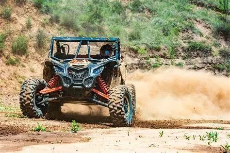
An all-terrain vehicle (ATV) is designed to go off-road. If a vehicle is described as an all-terrain vehicle, it usually has four-wheel drive, high ground clearance and the big Tyres needed to tackle all types of terrain, as the name suggests. An ATV can go places that a road car can’t: fields, hills, rocks, rivers, mud.
An all-terrain vehicle can be used for pleasure – either as a means of getting to a back-country destination or to the perfect fishing spot, or for the fun of putting a vehicle over a challenging track involving deep mud, ruts and slopes that a non-ATV would be incapable of.
All-terrain vehicles are also used as work vehicles, often by forestry workers or farmers. ATV vehicles are often fitted with differential gearing and low-ratio gearing to improve traction and grip in slippery conditions.
CVT Continuously Variable Transmission:
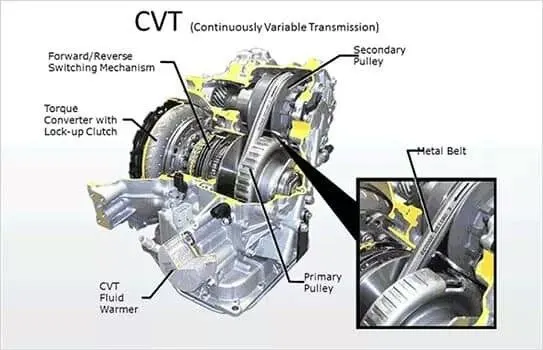
A CVT or Continuously Variable Transmission is an automatic, single speed, and gearless transmission that can shift through an infinite number of gear ratios. A continuously variable transmission (CVT) is a transmission that operates on an ingenious pulley system that automatically varies the transmission ratio, allowing an infinite variability between highest and lowest gears with no discrete steps or shifts. CVTs provide more useable power, better fuel economy and a smoother driving experience than traditional transmissions that use gearboxes with fixed numbers of gear sets.
About Baja Sae:
Baja SAE is a Collegiate Design Series competition run by the Society of Automotive Engineers International (SAE International). Teams of students from universities all over the world design and build small off-road cars. The cars all have engines of the same specifications. As of 2018 the engine has been an unmodified Briggs & Stratton Model 19 Vanguard engine single cylinder with a displacement of 305cc and power output of approximately 10 bhp (7.5 kW).
The goal in Baja SAE racing is to design, build and race off-road vehicles that can withstand the harshest elements of rough terrain. The vehicles used in Baja SAE racing are often similar in appearance to dune buggies. Before 2007, the events were called Mini Baja.
MAIN BLOCKS USED:
Generic Engine block:
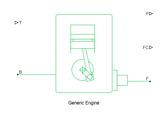
The Generic Engine block represents a general internal combustion engine. This block is a suitable generic engine for spark-ignition and diesel. Speed-power and speed-torque parameterizations are provided. A throttle physical signal input specifies the normalized engine torque. Optional dynamic parameters include crankshaft inertia and response time lag. A physical signal port outputs the engine fuel consumption rate based on the fuel consumption model that you choose. Optional speed and redline controllers prevent engine stall and enable cruise control.
SIMPLE GEAR:
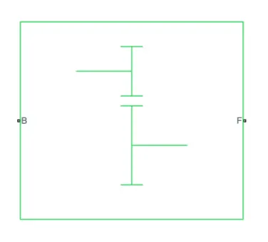
The Simple Gear block represents a gearbox that constrains the connected driveline axes of the base gear, B, and the follower gear, F, to corotate with a fixed ratio that you specify.
Main ports:
B-Base: Rotational mechanical conserving port associated with the base, or input, shaft.
F- Follower: Rotational mechanical conserving port associated with the follower, or output, shaft.
Variable Ratio Transmission block:
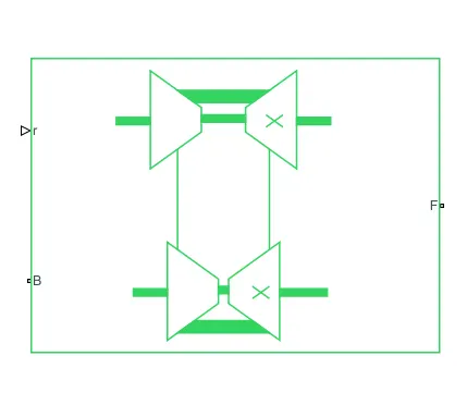
The Variable Ratio Transmission block represents a gearbox that dynamically transfers motion and torque between the two connected driveshaft axes, the base and the follower.
Transmission compliance introduces internal time delay between the axis motions. Unlike a gear, a variable ratio transmission does not act as a kinematic constraint. You can also control the torque loss caused by transmission and viscous losses.
Vehicle Body block:
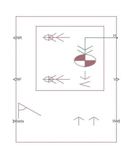
The Vehicle Body block represents a two-axle vehicle body in longitudinal motion. The vehicle can have the same or a different number of wheels on each axle. For example, two wheels on the front axle and one wheel on the rear axle. The vehicle wheels are assumed identical in size. The vehicle can also have a center of gravity (CG) that is at or below the plane of travel.
The block accounts for body mass, aerodynamic drag, road incline, and weight distribution between axles due to acceleration and road profile. Optionally include pitch and suspension dynamics. The vehicle does not move vertically relative to the ground.
The block has an option to include an externally-defined mass and an externally-defined inertia. The mass, inertia, and center of gravity of the vehicle body can vary over the course of simulation in response to system changes.
The Vehicle Body block lets you model only longitudinal dynamics, parallel to the ground and oriented along the direction of motion. The vehicle is assumed to be in pitch and normal equilibrium. The block does not model pitch or vertical movement. As such, the equations assume that the wheels never lose contact. This constraint can result in negative normal forces.
INPUTS:
- W — Headwind speed, m/s scalar Physical signal input port for headwind speed.
- beta — Road incline angle, rad scalar: Physical signal input port for road incline angle.
- CG — Center of gravity, m: two-element vector: Physical signal input port for the center of gravity, in m, of the externally-defined mass relative to the CG of the vehicle body.
- M — Mass, kg scalar: Physical signal input port for the mass, in kg, of the externally-defined mass.
- J — External moment of inertia, kg*m^2 scalar: Physical signal input port for the moment of inertia, in kg*m^2, of the externally-defined mass.
OUTPUTS:
- V — Longitudinal velocity, m/s scalar: Physical signal output port for vehicle longitudinal velocity in the vehicle reference frame.
- NF — Front axle normal force, N scalar: Physical signal output port for normal force on the front axle. Wheel forces are considered positive if acting downwards.
- NR — Rear axle normal force, N scalar: Physical signal output port for normal force on the rear axle. Wheel forces are considered positive if acting downwards.
- H — Horizontal motion mechanical translational: Conserving port associated with the horizontal motion of the vehicle body. Connect tire traction motion to this port.
Double shoe brake block:
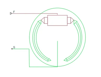
The Double-Shoe Brake block represents a frictional brake with two pivoted rigid shoes that press against a rotating drum to produce a braking action. The rigid shoes sit inside or outside the rotating drum in a diametrically opposed configuration. A positive actuating force causes the rigid shoes to press against the rotating drum. Viscous and contact friction between the drum and the rigid shoe surfaces cause the rotating drum to decelerate.
Double-shoe brakes provide high braking torque with small actuator deflections in applications that include motor vehicles and some heavy machinery. The model employs a simple parameterization with readily accessible brake geometry and friction parameters.
You can also enable faulting. When faulting occurs, the belt will exert a user-specified force. Faults can occur at a specified time or due to an external trigger at port T.
Input ports:
F- Physical signal input port associated with the applied actuating force
Conserving ports:
S- rotational conserving port associated with the rotating drum shaft.
Tire (magic formula):
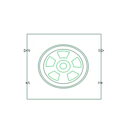
The Tire (Magic Formula) block models a tire with longitudinal behavior given by the Magic Formula [1], an empirical equation based on four fitting coefficients. The block can model tire dynamics under constant or variable pavement conditions.
The longitudinal direction of the tire is the same as its direction of motion as it rolls on pavement. This block is a structural component based on the Tire-Road Interaction (Magic Formula) block.
To increase the fidelity of the tire model, you can specify properties such as tire compliance, inertia, and rolling resistance. However, these properties increase the complexity of the tire model and can slow down simulation. Consider ignoring tire compliance and inertia if simulating the model in real time or if preparing the model for hardware-in-the-loop (HIL) simulation.
OTHER BLOCKS USED:
1)Solver configuration
2)Signal builder
3)Simulink to PS converter
4)PS to Simulink converter
5)Mechanical Reference
6)Rotational free end
7)Scope
8)Display
9)Inertia
10)Rotational motion sensor
11)PS terminal
12)PS constant
13)Rotational free end
14)Custom measure gauge
15)Knob
16)Lookup table
17)Step
TYPES OF MODELS:
- BAJA ATV model without dashboard
- BAJA ATV model with dashboard
- BAJA ATV model –mapped lookup table with dashboard
BAJA ATV MODEL WITHOUT DASHBOARD( cvtModel)
MAIN MODEL:
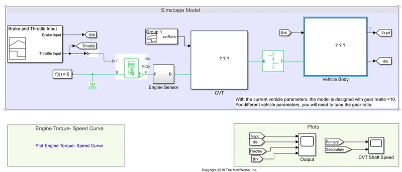
- The throttle signal is generated by signal builder block and inputted to generic engine.
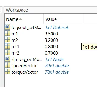
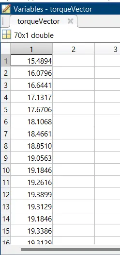
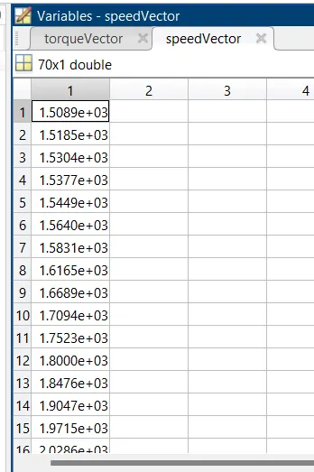
- The torque and speed vector are inputted from the MATLAB workspace
- The engine will generate the output rpm which can be taken from the crankshaft output. The speed will be given to the ideal rotational motion sensor to sense the output rpm.
- The same output speed will be given a simple to a simple gear mechanism to reduce the speed where the gear ratio is 4.
- Then the output speed from the gear reducer will be given to the variable ratio transmission block (CVT)
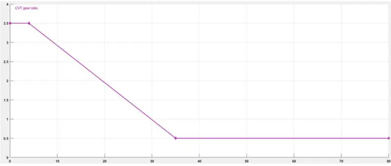
- The CVT ratio is provided to the variable ratio transmission (CVT) block through signal builder.
- The speed is controlled by the variable CVT ratios and the controlled output speed is inputted to the vehicle axle.
- The brake signal is generated by the signal builder and inputted to the vehicle body for applying the brake to axle.
- The power from the CVT is inputted to the axle and the vehicle accelerates according to the speed.
- Then the velocity is taken as output from the vehicle body for further analysis.
INPUT SIGNAL:
Throttle & Brake input signal:
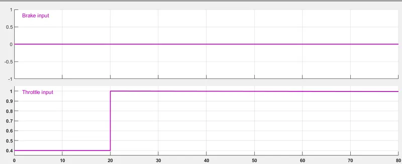
Throttle starts at 0.3 and then it steps to 1 at the 20th second and the brake input remains zero through the whole simulation.
OUTPUT:
TORQUE-SPEED PLOT:
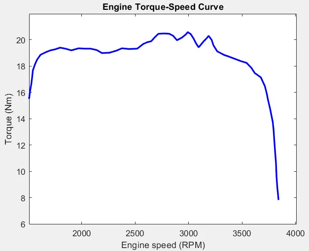
The torque and speed are inputted from the MATLAB workspace window to the generic engine block to generate the output RPM accordingly. This plot behavior is generic to all ICE.
Engine speed plot:
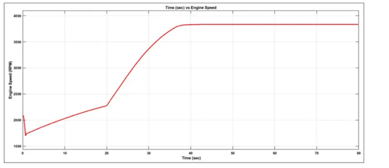
Engine rpm generated accordingly w.r.t. to the throttle, speed and torque inputs.
ENGINE SPEED vs GEAR REDUCTION SPEED PLOT:
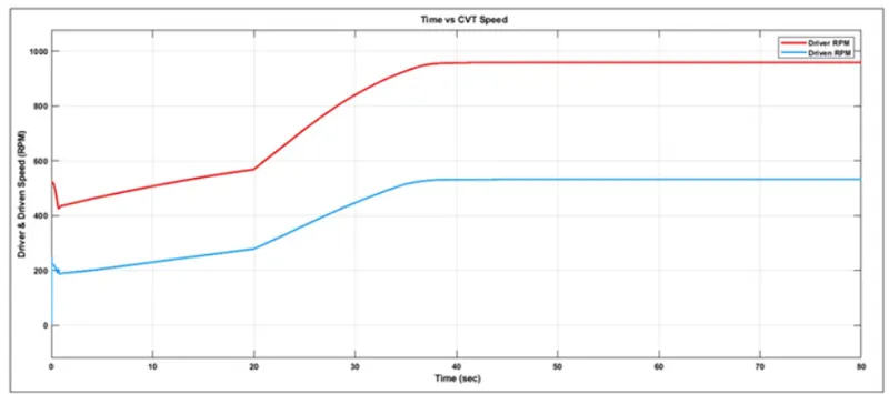
The engine speed is reduced by the gear ratio ’4’. For verification calculating the maximum RPM
Maximum RPM (before reducing) =3833 rpm
Gear Ratio=1:4
We know that,
Driven = 3833/ 4
Driven = 95625RPM
Thus, the reduced maximum rpm is 958.25rpm which can be verified from the plot.
Driven= secondary CVT shaft
Driver = Primary CVT shaft
CVT SPEED REDUCTION PLOT:
SPEED VS THROTTLE PLOT:
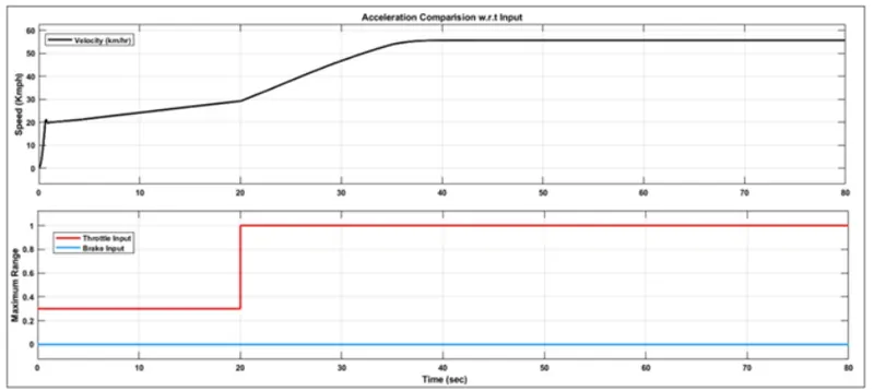
The brake is not applied during the drive cycle and the throttle is constant (0.3) till 20 sec and being increased from 0.3 to 1 from 20 sec where it remains constant for the rest of the run. With the increase in throttle, the vehicle speed also increases.
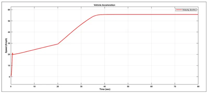
ACCELERATION PLOT:
BAJA ATV MODEL WITH DASHBOARD
MAIN MODEL:
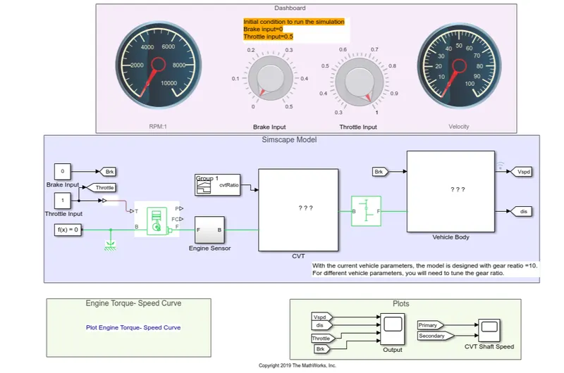
The model workflow process is as same as the process of BAJA ATV model without dashboard but the Throttle and Brake inputs are controlled by the user with the knob. We are also replacing signal builder with two separate constant blocks for throttle and brake.
ENGINE SPEED PLOT:
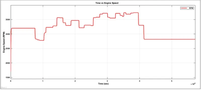
The engine speed is generated according to the inputs like throttle, brake, torque and speed vectors. The runtime is not defined so that the throttle and brake are controlled by the user. The step up is throttle and step down are brake inputs.
ENGINE SPEED VS GEAR REDUCTION SPEED PLOT:
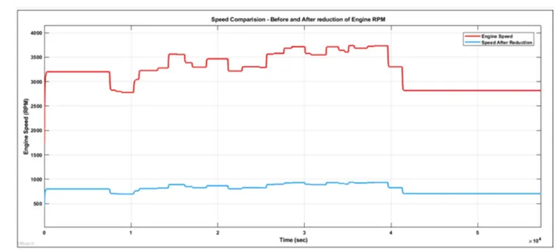
The engine speed is reduced by the gear ratio ‘4’. For verification I calculated the constant RPM (42000 – 50000 sec). Maximum RPM (Before reducing) = 2759.3 rpm
Gear Ratio = 1:4
We know that,
Driven = 2759.3/4
Driven = 689.825 RPM
The reduced constant rpm is 689.825 rpm which can be verified from the plot.
SPEED vs THROTTLE PLOT:
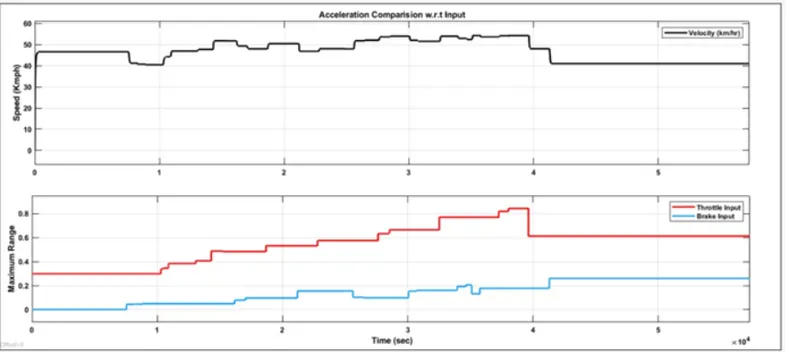
From the graph we can infer that the vehicle is accelerating while throttle is applied as (step up) and decelerated while break is applied (step down).
ACCELERATION PLOT:
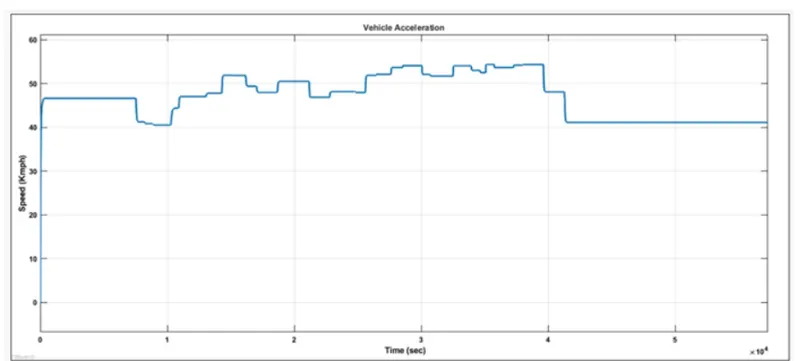
We can say that the vehicle is accelerated to 46 kmph initially and then the state changes when the user controls the throttle and brake knobs. The step-up and step-down are acceleration and deceleration respectively. The linear one is the constant speed so no changes in throttle or braking.
BAJA ATV MODEL- MAPPED LOOKUP TABLE WITH DASHBOARD
SIMULINK MODEL:
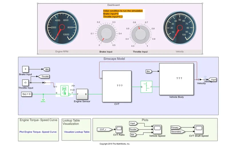
DASHBOARD MODEL (SIMULATION OFF):
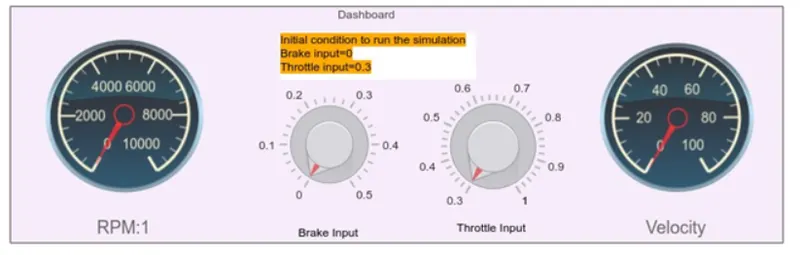
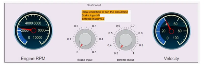
DASHBOARD MODEL (SIMULATION ON):
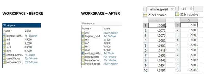
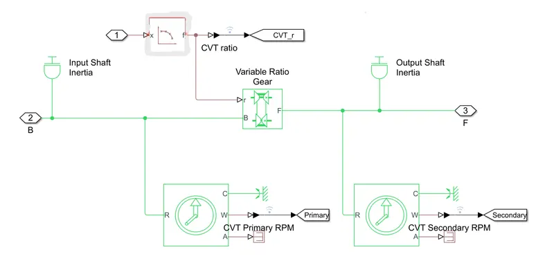
Instead of a signal builder block for CVT ratio the2-D lookup table is used. The interpolation and extrapolation methods are set to linear.
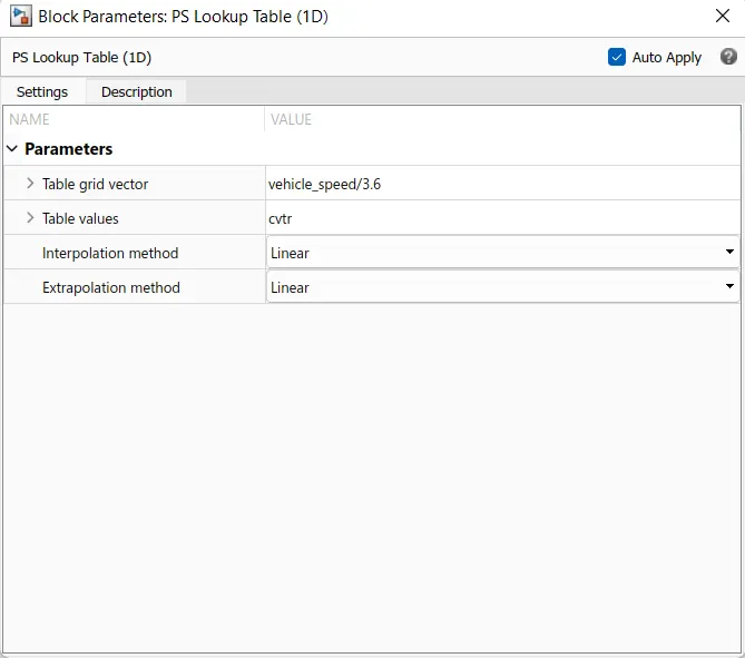
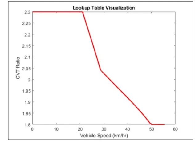
Right click on the lookup table block and choose foundation library option and then plot option to visualize the lookup table.
RELATIONSHIP OF CVT RATIO, THROTTLE AND BRAKE INPUTS:
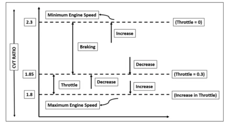
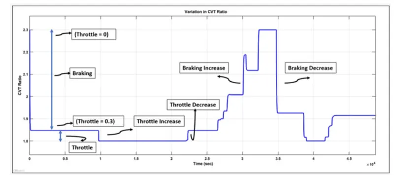
In this BAJA ATV MODEL, the engine is pre-set to run at 3000rpm with the throttle value of 0.3. And the velocity at 45 m/s. The CVT ratio for minimum and maximum speed of the engine was pre-defined as 2.3 and 1.8 respectively. When the simulation is started the initial throttle value 0.3 is achieved so that the CVT ratio is nearby to 1.85. When the throttle is being increased the CVT ratio move towards 1.8 where the state is maximum engine speed. When braking is reduced the CVT ratio move towards 1.85 which is the basic throttle input 0.3 or if any other throttle value is applied it would reach that CVT ratio state.
CVT RATIO PLOT:
OUTPUT: -
ENGINE SPEED PLOT: -
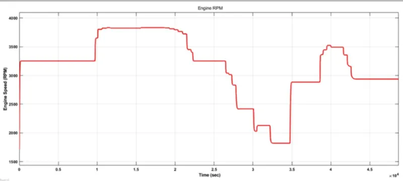
From the graph we can infer that the vehicle was first running at minimum rpm of 3300 rpm and then throttle is applied step-up then braking step down then brake is released so that engine rpm is increased then braking is applied. Finally throttle and brake are put to constant of 2900 rpm.
CVT SPEED PLOT:
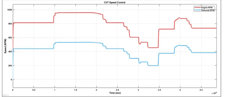
From the above graph we can understand that the throttle is applied step-up and then kept constant, then braking is applied (step-up) and then kept constant, then braking is applied (step-down), and brake is released and engine speed is increased with the increase in throttle input.
INPUT vs VEHICLE SPEED:
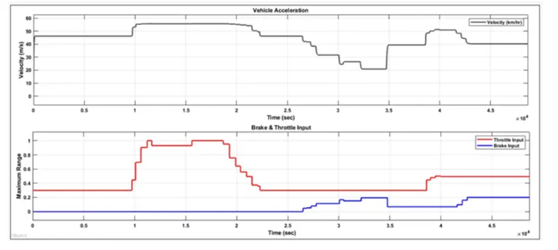
When throttle is applied the vehicle speed increases and when brake is applied, vehicle speed decreases simultaneously.
SIMULINK MODEL:
BAJA ALL-Terrain Vehicle (ATV) model – file exchange- MATLAB Central (mathworks.com)