Week-7 Challenge: DC Motor Control
AIM(1):-(A). Explain a MATLAB demo model named ‘Speed control of a DC motor using BJT H-bridge’.
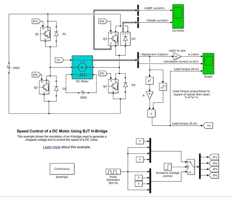
- When the BJT is conducting i.e. operating in the saturated region, there will be a forward voltage developed between the collector and the emitter. An lGBT is Used to model the BJT because of this.
- The switch is controlled by a Simulink signal. The DC motor used in this model with specifications: 5HP, 24v, 1750rpm.It simulates a fan type load where the load is proportional to the square of the speed.
- The mean armature voltage can be varied between 0 and 240v when the duty cycle is changed anywhere from 0 to 100%. The duty cycle can be changed from the pulse generator block.
- The H-bridge consists of 4 BJT and Diode pairs.Two transistors are switched on simultaneously Q1 and Q4 or Q2 and Q3. When Q1 and Q4 are fired, a positive voltage is applied to the motor and the diodes, D2 and D3 operate as free wheeling diodes when Q1 and Q4 are switched off.
- Similarly, when Q2 and Q3 are fired, a negative voltage is applied to the motor and the diodes, D1 and D4 operate as free wheeling diodes when Q2 and Q3 are switched off.
- By default, the motor will start in the positive direction and has a preset duty cycle of 75% with a mean DC voltage of 180v. At t = 0.5 seconds, the armature voltage will reverse and the motor will run in the negative direction.
(B)Comment on the armature current shoot-up from the scope results.
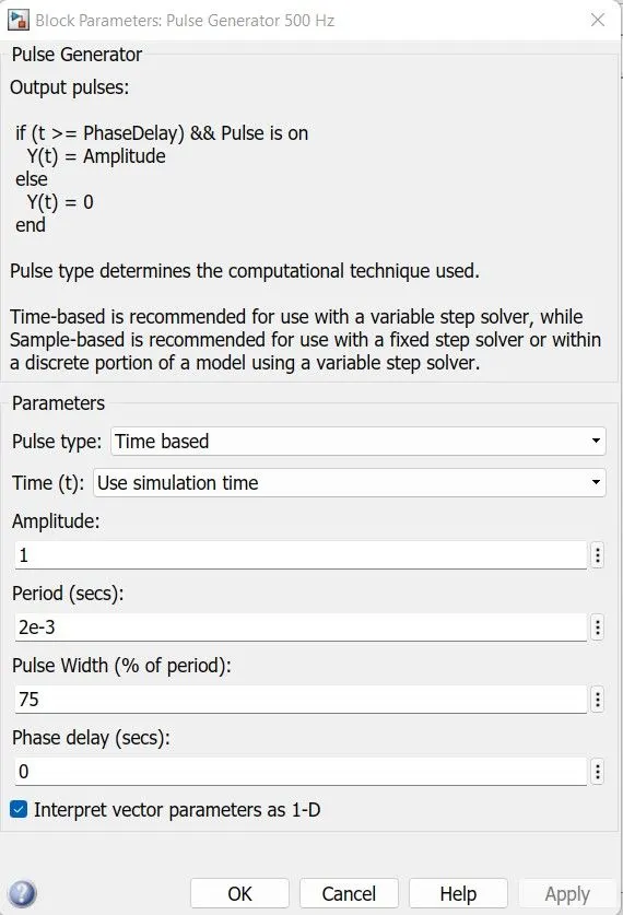
- As we can see, the pulse generator is already set with some settings. The pulse width field allows us to modify the duty cycle of the motor and hence, we can prevent the motor current from shooting up when the motor changes its direction from forward to reverse.
- By default the duty cycle is 75% meaning that the voltage is supplied to the motor for 75% of the time for one cycle. For the remaining 25%, the motor is off and receives no voltage from the source.
- This alternation between the ON and OFF states,that allows us to vary the voltage that is supplied to the motor and thereby control the speed of an electric vehicle.
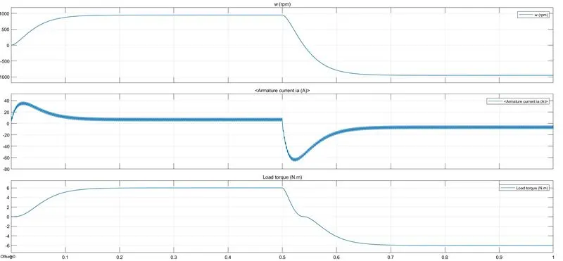
- Above image shows the Output of the scope when the simulation is run using the preset values in the pulse generator block. There are 3 output graphs of angular speed, armature current and the load torque all against with time.
- Here,we are interested in modifying the simulation in order to prevent the initial shoot up of the armature current at the start of the cycle. This shoot up occurs whenever the armature voltage goes into reverses direction which is every 0.5 seconds.
- As shown in second graph i.e armature current vs. time,we can see that at the start of the cycle, there is a sharp increase in the armature Current then decreases and comes to a more stable level where it remains until 0.5 seconds.
- When the next cycle begins, the exact same effect Occurs but in the negative axis in this cycle because the armature voltage is reversed.
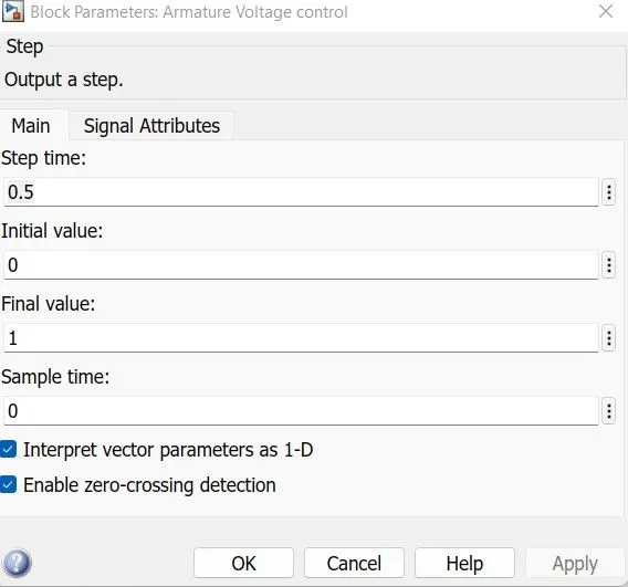
- This frequency of reversing the voltage direction has been preset in the armature voltage control block. Opening it will give you a dialog box of its setting where the 'step time' field controls the frequency at which the voltage is reversed.
- If we change the duty cycle i.e. the pulse width,we can control this initial shoot up of the current that occurs every time the armature voltage direction is reversed. When the duty cycle is decreased to 50% the output graph that is obtained is shown below.
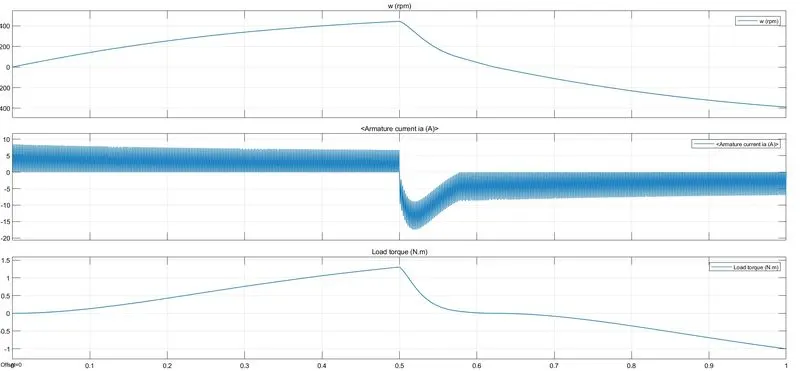
- For the 50% duty cycle,we can see that armature current does not shoot up initially for the positive direction of the armature voltage.However, after the 0.5 second when the armature voltage is reversed, the armature current shoots up in the negative direction. So,we need to decrease the duty cycle further to prevent this.
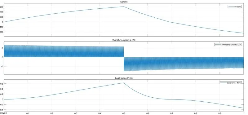
- This time, I have reduced the duty cycle to 40%.The output graph is shown above.
- Here, we can see that at the start of the cycle in the positive armature voltage direction, the armature current does not shoot up like it did for 50 and above duty cycle.The armature current increases immediately to approximately 7A and it maintains that level until the next cycle where the armature voltage is reversed to -7A.
(C)Refer to the help section of ‘The Four-Quadrant Chopper DC Drive (DC7) block’. Compare it with the H-bridge model.
- The Four-Quadrant Chopper DC Drive (DC7) block represents a four-quadrant, DC-supplied,chopper (or DC-DC PWM converter) drive for DC motors.
- This drive features closed-loop speed control with four-quadrant operation. The speed control loop outputs the reference armature current of the machine. Using a PI current controller, the chopper duty cycle corresponding to the commanded armature current is derived.
- This duty cycle is then compared with a sawtooth carrier signal to obtain the required PWM signals for the chopper.
- The Four-Quadrant Chopper DC Drive block uses these blocks from the Electric Drives/Fundamental Drive Blocks library:
- Speed Controller (Dc)
- Regulation Switch
- Current Controller (DC)
- Chopper
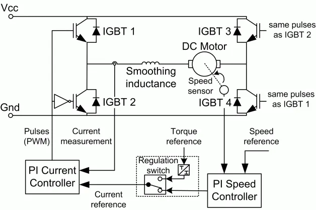
- The above figure shows the schematic of the four quadrant chopper DC drive.
- Comparsion of H-bridge & Four Quadrant chopper DC drive:-
- Only Two quadrants of operation are possible in H-bridge.They are Forward motoring and reverse motoring.
- Four quadrant dc chopper can operate in all four quadrants (forward motoring., reverse generation, reverse motoring. and forward regeneration).
- Higher armature current ripple in H-bridge.
- Lower armature current ripple due to high switching frequency of DC-DC coverters in four quadrant chopper dc drive.
- H-bridge Less complex.
- Four Quadrant chopper DC drive More complex.
- Simulation is continuous and simulation time is more for H-bridge.
- Discrete and Simulation time is less for Four Quadrant chopper DC drive.
- H-bridge Widely Used in Robotics.
- Four Quadrant chopper DC drive Widely used in Automobile.
AIM(2):-Develop a 2-quadrant chopper using simulink & explain the working of the same with the relevant results. (Refer to article - Multiquadrant operation of motor )
- Type C chopper or Two Quadrant class A chopper:
- Class-C or Type-c chopper is a category of chopper which can operate in first as well as second quadrant. This basically means that the power can either flow from source to load or load to source in this chopper. This kind of chopper is also known as Two Quadrant class-A chopper.
- Working of class C chopper:-
- As we know that, a Class A and Class B chopper operates in first and second quadrant respectively. Therefore, If We connect both these types of chopper in parallel then it is possible to have chopper operation in first as well as second quadrant.
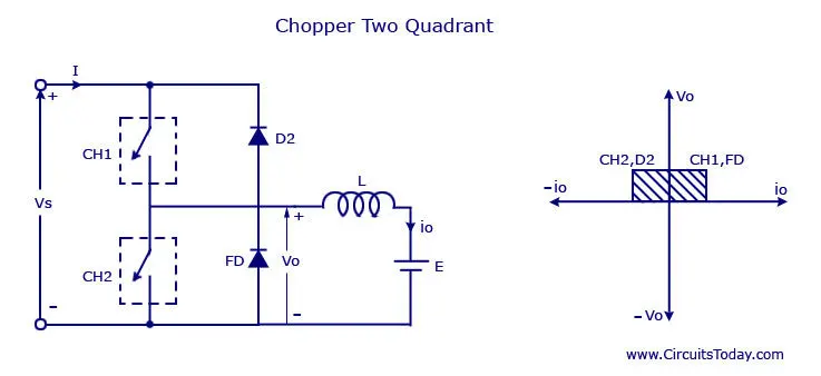
- In fact, Class-C or Type-C chopper is obtained by the parallel connection of Class-A and class-B chopper. Figure below shows the circuit diagram of this type of chopper.
- We can notice that chopper CHI, free-wheeling diode (FD) and load are forming class-A Chopper whereas chopper CH2, D2 and Load are forming Class-B chopper. Both these choppers are connected in parallel.
- To obtain first quadrant operation we should switch ON chopper CHI and for getting second quadrant operation we should switch ON chopper CH2.
- Let us discuss this in detail.
- Case 1 When Ch1 is switched ON/OFF:-
- When chopper Ch1 is switched ON, source directly gets connected to the load , load and hence voltage Vs is equal to source voltage. The direction of load current is from source to load as shown in the Circuit diagram which is assumed positive.
- When CH1 is Switched off, the free-wheeling diode FD Comes into the circuit as it gets forward biased and hence shorts the load.Therefore, the output voltage V, becomes zero.However, the is continues to die down through the FD and L in the same direction as shown in Circuit diagram. Thus, the average output voltage Vo and current l are positive and hence operation of chopper is in first quadrant.
- Case 2 When CH2 IS Switched ON/OFF:-
- When chopper CH2 is switched ON, load DC source E drives current through CH2 and load. The direction of this current io will be opposite to that shown in circuit diagram and hence is assumed negative. Output voltage V, is zero during this time. when CH2 is made OFF, diode D2 gets forward biased and hence the current into the source from the load.
- The output voltage is Vs in this time as the load is connected to the source through D2 during off time of chopper CH2. Thus, the load current is always negative i.e. operation of chopper is within second quadrant.
- The average load voltage is always positive but the average load current may be positive or negative. Therefore, power flow may be from source to load (first quadrant operation) or load to source (second quadrant operation).The operating region of Class-C or Type-c chopper is shown above by hatched area.
- SIMULINK MODEL:-
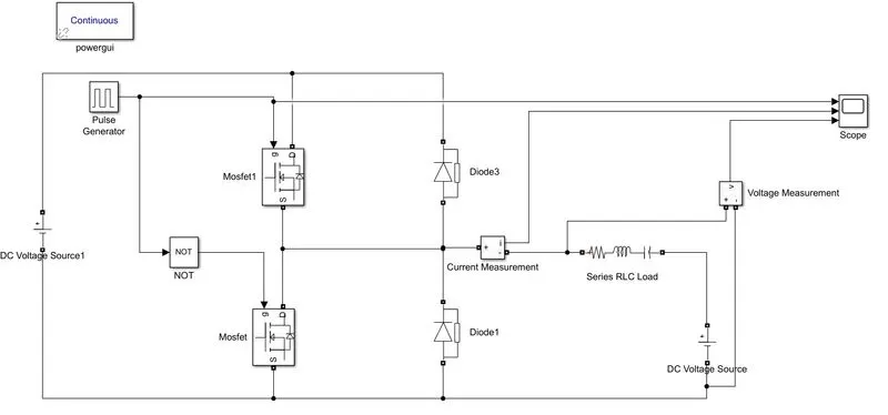
- As shown in above model,we are using mosfet as switching devices and diode for continuos flow.
- Here, we are using pulse generator for giving gate pulses to the mosfet.NOT gate is using for give the signal one after another.
- Series RLC load is connected to the system.Current mesurement and voltage mesurement block are used for readings.
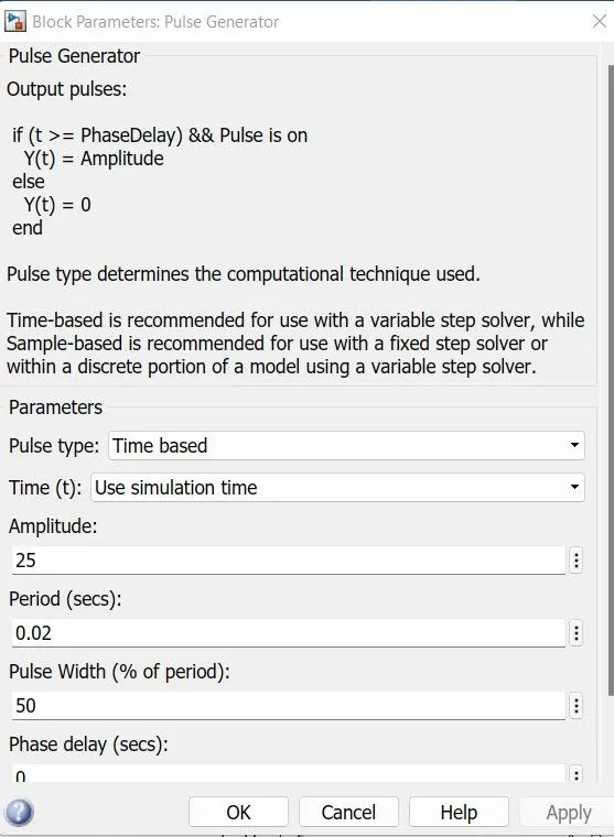
- As shown in above pulse generator block we are giving the value of amplitude 25,period 0.02,pulse width 50%.
- OUTPUT:-
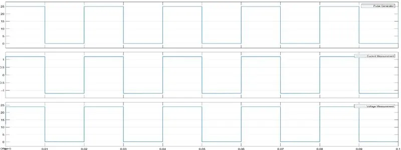
- We could see clearly that the voltage is always positive but the current becomes both positive and negative.Hence,The type C Chopper is simulated and verified.
AIM(3):-Explain in a brief about operation of BLDC motor.
- Brushless DC electric motors also known as electronically commutated motors.Primary efficiency is a most important feature for BLDC motors. Because the rotor is the sole bearer of the magnets and it doesn’t require any power. i.e. no connections, no commutator and no brushes.
- In place of these,the motor employs control circuitry. To detect where the rotor is at certain times, BLDC motors employ along with controllers, rotary encoders or a Hall sensor.
- Construction:-
- In this motor, the permanent magnets attach to the rotor. The current-carrying conductors or armature windings are located on the stator.They use electrical commutation to convert electrical energy into mechanical energy. The main design difference between a brushed and brushless motors is the replacement of mechanical commutator with an electric switch circuit.
- A BLDC Motor is a type of synchronous motor in the sense that the magnetic field generated by the stator and the rotor revolve at the same frequency.
- Brushless motor does not have any Current carrying commutators. The field inside a brushless motor is switched through an amplifier which is triggered by the commutating device like an optical encoder.
- Working:-
- BLDC motor works on the principle similar to that of a Brushed DC motor. The Lorentz force Law which states that whenever a Current carrying conductor placed in a magnetic field it experiences a Force.
- As a Consequence of reaction force,the magnet will experience an equal and opposite force. In the BLDC motor, the Current carrying conductor is stationary and the permanent magnet is moving.
- When the stator coils get a supply from source,it becomes electromagnet and starts producing the uniform field in the air gap.
- Though the source of supply is DC, switching makes to generate an AC voltage waveform with trapezoidal shape. Due to the force of interaction between electromagnet stator and permanent magnet rotor, the rotor continues to rotate.
- CONCLUSION:-
- Using H bridge we can run motor in Forward motoring and reverse motoring.
- Using DC7 block we can run motor in all four quad
- Using type c chopper we can run motor in first and second quadrant.
- Construction of BLDC motor.