Project
- AIM:-To know about basic vehicle modelling using BAJA ATV CVT based models and observe their result.Also write a techincal Report of your observation.
- OBJECTIVE:-
- Engine
- CVT(Continuously Variable Transmission)
- Vehicle Body
- Tire
- suspension
(1)OPENLOOP BASED:-
- SIMULINK MODEL:-
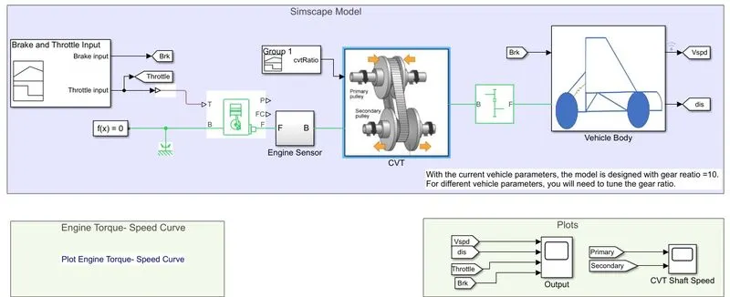
- As Shown in above model,it contains Signal builder,engine block,simple gear,cvt block and vehicle body.
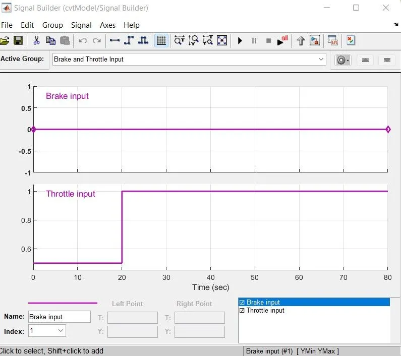
- Here signal builder is used for give the inputs of throttle and brake signal to the generic engine and vehicle body respectively.
- As shown in above we are giving brake input as zero and throttle as 0.3 before 20 sec and 1 after 20 sec.
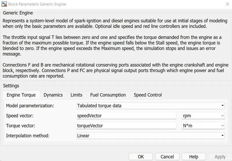
- Generic engine block is used to programmed relation between speed and torque by applying some trottle input at T port.
- So, here inside of generic engine we are giving some input as speedvector and torque vector by extracting the data point of speed-torque.
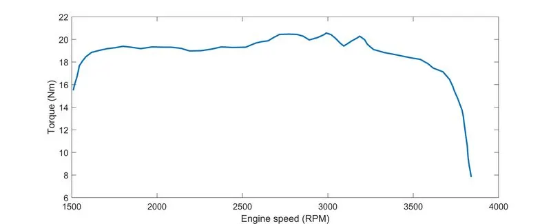
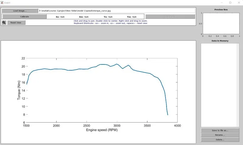
- So,by using grabit we can easily extract the data point form any image.That data points are feeded to the generic engine block.
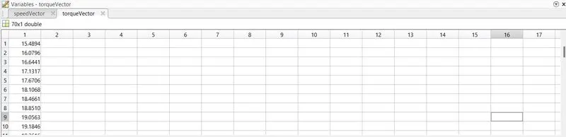
- So, we get the data points like this in .mat file.
- Continuously Variable Transmission:-
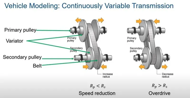
- As shown in above figure,it consist of primary pulley,variator,secondary pulley and belt.
- In case 1, the variator of primary pulley goes outward and veriator of secondary pulley goes inward it means radius of secondary pulley is goes higher than primary pulley. its called speed reduction.
- In case 2,the variator of primary pulley goes inward and veriator of secondary pulley goes outward it means radius of secondary pulley is goes less than primary pulley. its called overdrive.
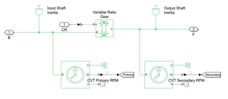
- As shown in above subsystem,there are two interia block that represents the primary and secondary pulley.
- Variable gear ratio is used for specifie the gear ratio of pulleys.
- There are two sensor at bottom of the subsystem which is ideal rotational motion sensor that measure the rpm of the primary and secondary pulleys.
- For speed reduction,we are connecting simple gear between cvt and vehicle body.
- Vehicle Body:-
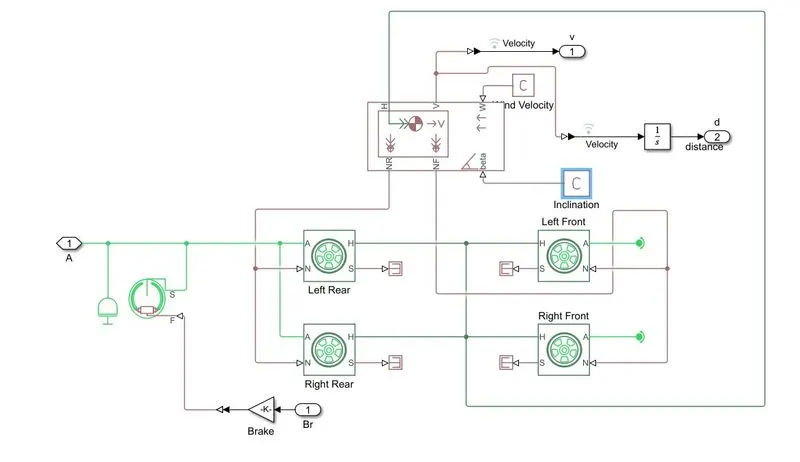
- The vehicle subsystem is consists of vehicle body,tires and brakes.
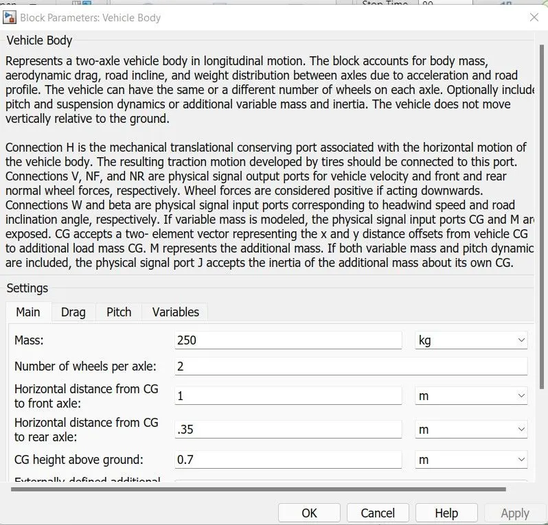
- As shown in above block parameter of vehicle body, we can easily load the data of our vehicle data i.e mass, number of wheels per axle etc.
- OBSERVATION:-
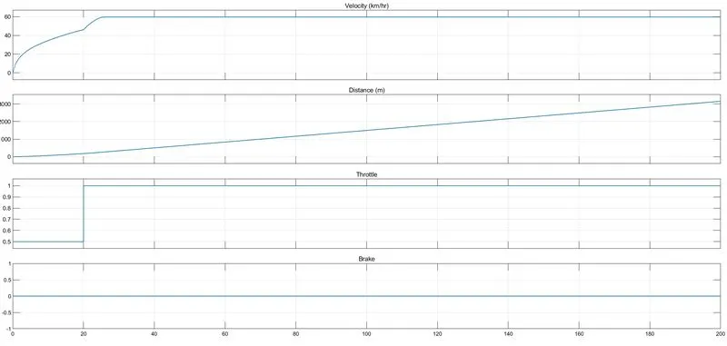
- As we run our simulation for 80 sec,we observe that velocity is start incresing and after 20 sec it will be constant.distance travelled by vehicle is shown.brake and throttle inputs are also shown.
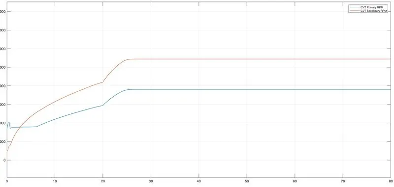
- We also see the primary and secondary pulleys rpm in above scope.we can see that after 25 sec the both pulleys speed is goes constant.
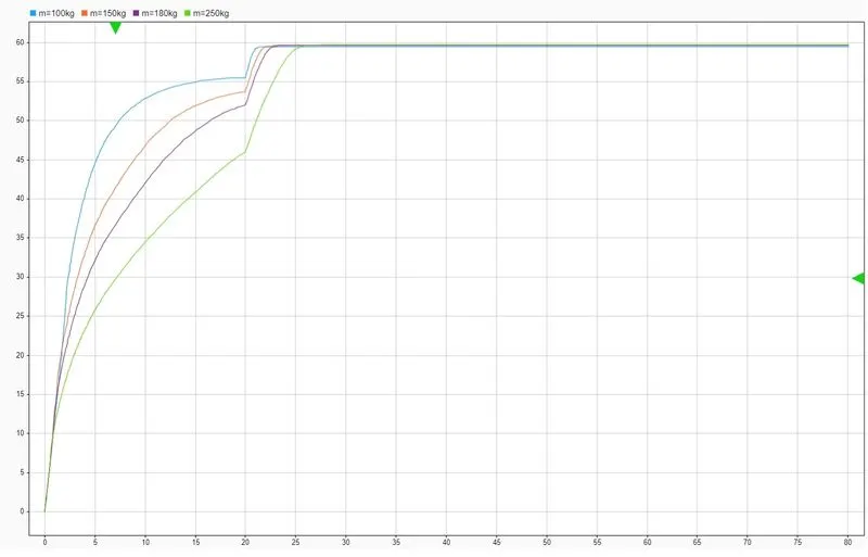
- As shown in above figure, which is speed vs time curve at different mass of vehicle.
- At the value of m=100kg, we get v=45km/hr in 5 sec but at value of m=250kg, we get v=km/hr in 5 sec.
- We can see that at lower value of vehicle mass, we get higher vehicle speed earlier.
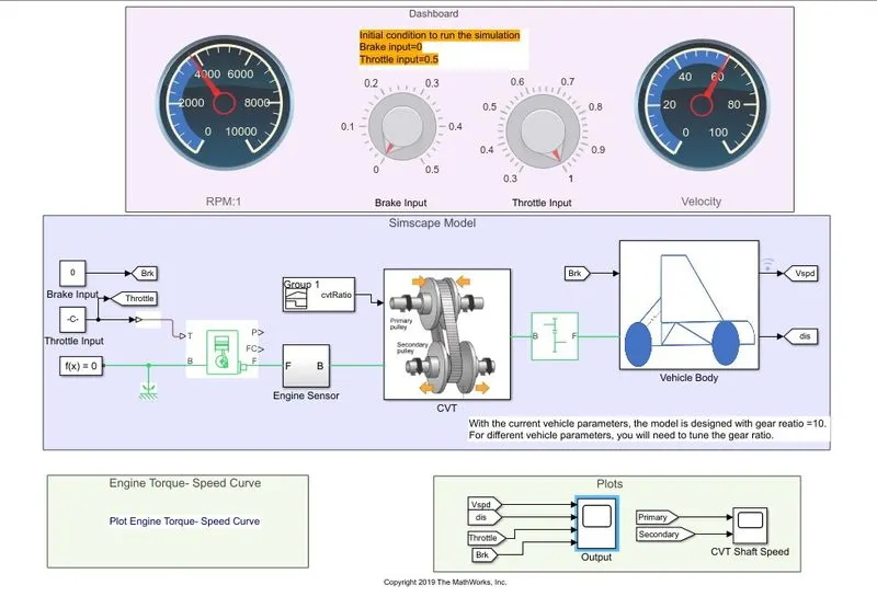
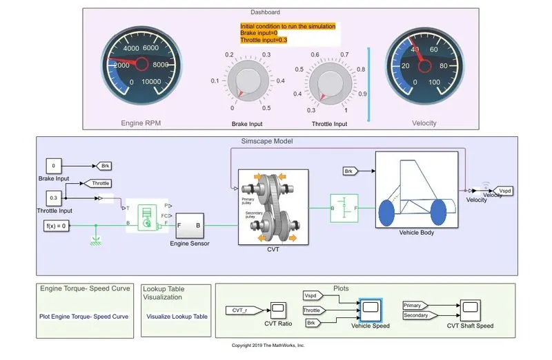
- As shown in above model, it is same as previous one but only change is we are using constant block for throttle and brakes and some konbs and gauges for indication of engine RPM and vehicle speed.
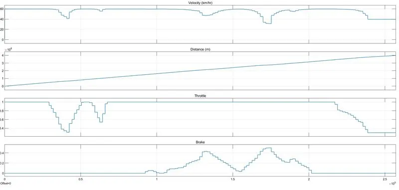
- when we run the simulation for infinite time,we can see that our vehicle speed is changing with changing of throttle and brakes inputs with help of knob.
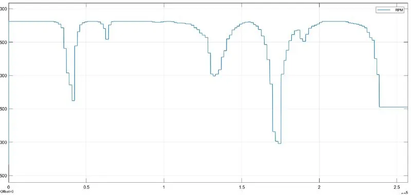
- The engine RPM is also changing by changing the throttle and brakes of the vehicle as we can see in above plot.
(2) CLOSED LOOP BASED:-
- SIMULINK MODEL:-
- SIMULINK MODEL DESCRIPATION:-
- As Shown in above model,we remove the cvt ratio signal bulider block and give the feedback signal from vehicle body which is velocity signal.
- This signal is control by the lookup table which is added in the cvt block.
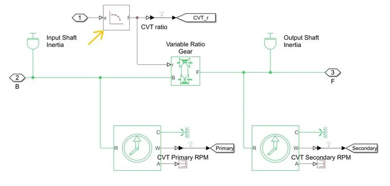
- Here is the lookup table,which block paramateris set by the vehicle speed and cvt ratio of the previous open loop model.
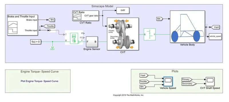
- As shown in above open loop model,we added two To workspace block for adding the values of vehicle speed and cvt ratio signal bulider block to our base workspace.
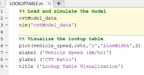
Fig.1
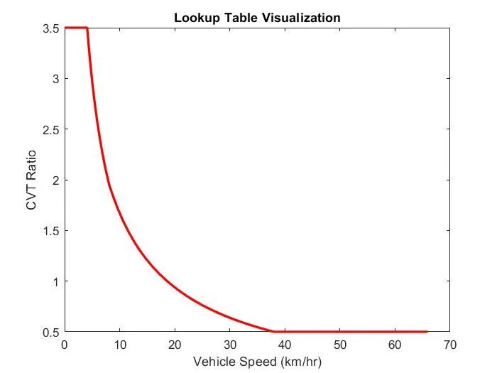
Fig.2
- As Shown in Figure 1, We write a script file for simulating the previous open loop model and plot the graph for vehicle_speed vs CVT_ratio.
- All data points of the above graph is given to the lookup table which is placed in CVT block
- OBSERVATION:-
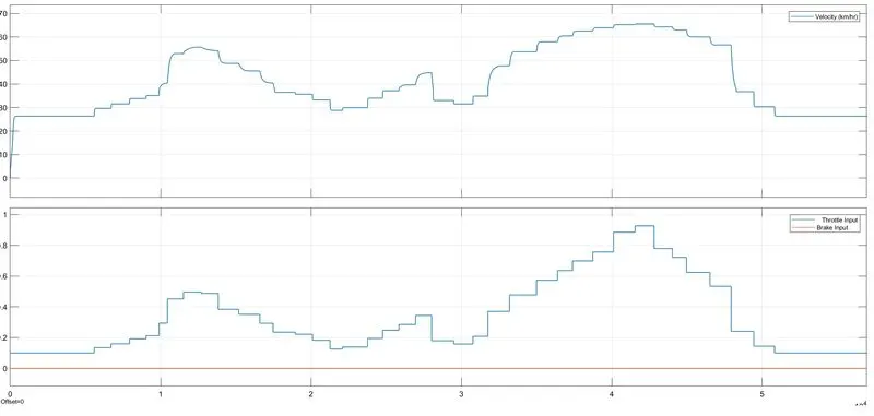
- As shown in above, we can see that when throttle is changing by knob our speed is changing with time.
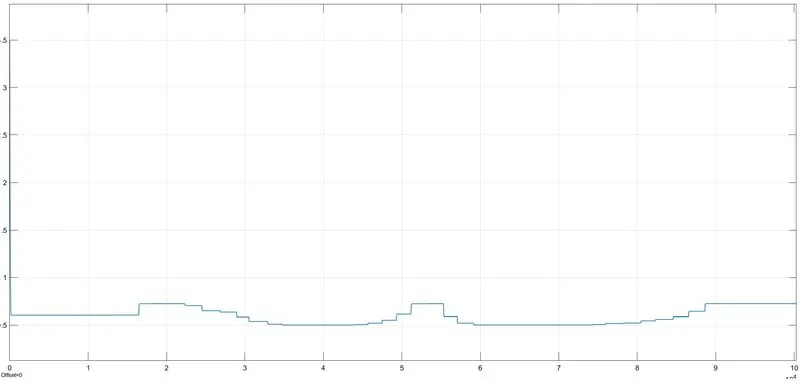
- So, by changing the speed our CVT ratio is also changing As shown in below scope.
- CONCLUSION:-
We concluded that we can easily get the all details for our practical model which is torque,speed,gear ratio etc.And also we can built our own model from all the above model as we discussed.