Week -2
1.AIM:-Make a Simulink model of Doorbell using solenoid block.
- SIMULINK MODEL:-
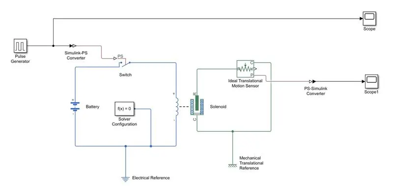
- SIMULINK MODEL DISCRIPATION:
- As shown in above model,we are using pulse generator for square wave signal generation at regular intervals.In this block configuration,we have to set the value of pulse width,period and phase dealy.
- simulink-PS convertor is use for convert the signal into physical block.
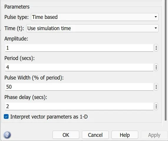
- As shown in above picture,we are giving 2 sec of phase dealy and peroid 4 sec as per requirement.
- switch block is controlled by external physical system,when it`s value is goes up to thershold then switch is closed and electrical input is given to the solenoid.
- fixed solver is used for solve the model at regular time intervals.
- Positive terminal of battery is connected to the positive terminal of switch and negative terminal of battery is connected to the electrical reference.
- Solenoid block is connected between switch and battery and will get complete electric circuit.The C port of solenoid is connected with mechanical reference.
- The R port of solenoid is connected to ideal translational motion sensor to observe the movement of plunger.
- Scope is connected with the ideal translational sensor to get the ouput.
- PS-Simulink converter is used to convert the physical signal to simulink signal.
- OBSERVATION:-
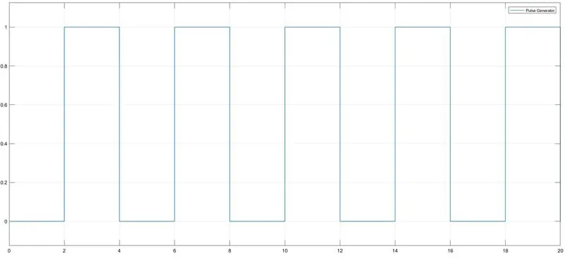
- As shown in figure 1,Time period is 2 sec to pulse generator to open and close the switch.when switch is closed the solenoid gets electrical power from battery and plunger move from R port to C to hit bell and produce sound.
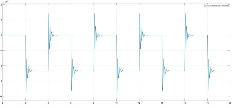
- As shown in above figure,the spikes are generated at every 2 sec.So that at every to 2 seconds we are getting movement from plunger.
- CONCULSION:-
So by using Solenoid block we can easily get output by giving input at electrical side of solenoid and also get pulnger movement of solenoid.
2.AIM:-Use a thermistor to sense the temperature of a heater & turn on or turn off the fan.
THERMISTOR:-
It works on principal of change in resistance due to a change in temperature.It made of semiconductor materials Such as nickel,manganese,copper,cobalt etc.
SIMULINK MODEL:-
SIMULINK MODEL DESCRIPATION:-
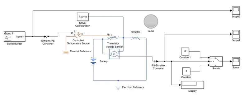
- Here,as shown in above figure,signal builder is used for built a signal as per requirement which is for 293 K from 0 to 10 seconds, 300 K from 10 to 30 seconds, 296 K from 30 to 50 seconds.
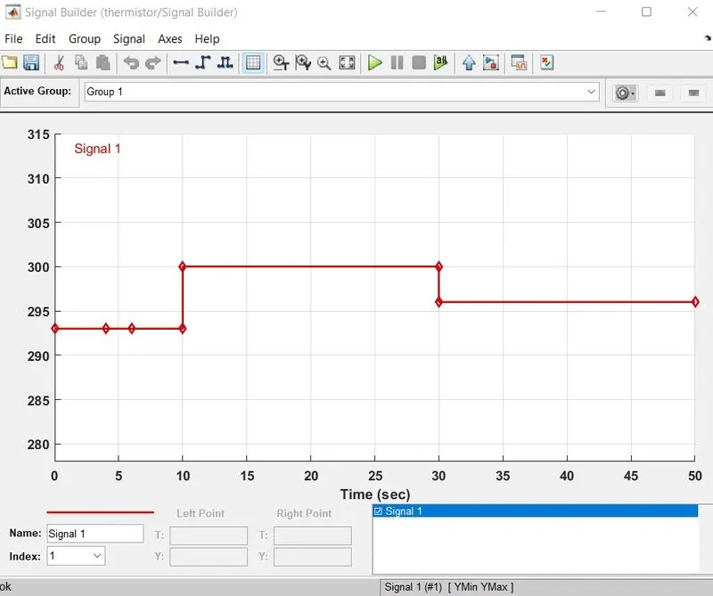
- Simulink - PS convertor is used to convert the simulink signal to physical signal.
- Controlled Temperature source represents an ideal source of thermal energy.physical input given to the port S of the block.A positive temperature difference causes the temperature at port B to be greater than the temperature at port A.
- Thermistor is a type resistor whose resistace is vary with the temperature.
- A linear resistance is used to control the amount of current from the battery.
- The positive terminal of battery is connected to the thermistor and negative teminal is connected to the electrical reference.
- Fixed solver is connected to the negative of thermistor to solve the model at regular time interval.
- Voltage sensor is connected parallel with the thermistor for sense the voltage across the thermistor.
- Output of volatge sensor is given to the PS-simulink convertor to convert the physical into simulink signal.
- Switch block is used for turn on and off the fun as per given conditon which is ON if the temperature above 25 °C(298k), OFF otherwise.
- Scopes are connected for observing the result.
- OBSERVATION:-
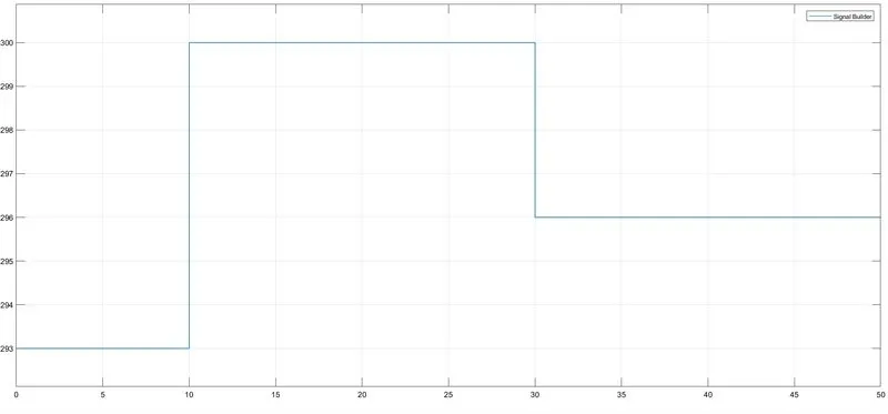
- From above figure, we are getting our signal from signal builder for 50 sec.
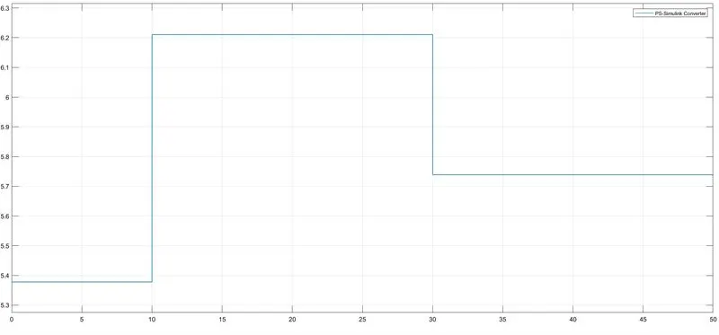
- From above result,the voltage of thermistor as per the time interval given to the signal builder.
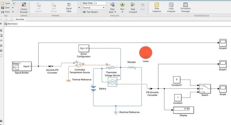
- When the simulink model is run for 9 seconds the lump is glow as red because the tempature for 0-10 second is 293 K i.e.below the 298 K. So that the fan is in off condition.
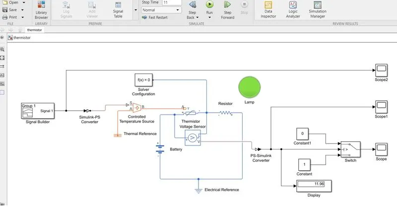
- When the simulink model is run for 11 seconds the lump is glow as green because the tempature for 10-30 second is 300 K i.e.Above the 298 K. So that the fan is in on condition.
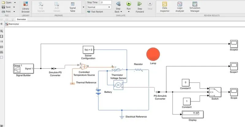
- When the simulink model is run for 31 seconds the lump is glow as red because the tempature for 30-50 seconds is 296 K i.e.below the 298 K. So that the fan is in off condition.
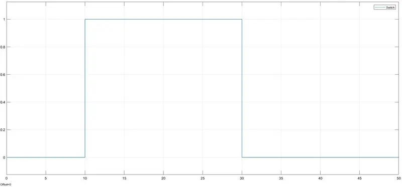
- From above result,we getting the switch output waveform for given fan on and off condition,for 0-10 seconds fan is off,10-30 seconds fan is on,30-50 seconds fan reamains off.
- CONCULSION:-
So by using this model we can easily trigger a fan for any time interval by building a signal of signal builder.