Project 1 (Mini Project on Vehicle Direction Detection
------------------------------------------EMD-BATCH-8---------------------------------------------------
Project 1 (Mini Project on Vehicle Direction Detection)
Objective of Mini Project:-
1. Development of MATLAB Simulink model as per requirement.
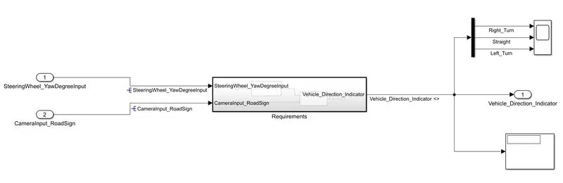
- Above is shown our main subsystem which is based on two given requirements. This main subsystem consists of two inputs and one output.
- Inputs are: SteeringWheel_
YawDegreeInput and CameraInput_RoadSign and Output is: Vehicle_Direction_ Indicator .
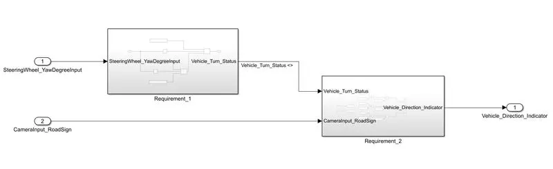
- Each of the inputs has separate Subsystems shown above.
- For input SteeringWheel_YawDegreeInput model is designed based on Requirement-1 using blocks of Constant and switch. It has output as Vehicle_Turn_Status which is fed into the input of a second subsystem based on Requirement-2 which is designed using blocks of Constant, Relational operator and Logical operator.
- Requirement-1:-
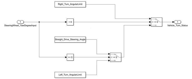
- Steering wheel input as yaw rate (Signal name: SteeringWheel_
YawDegreeInput) is the input for this system. - This is compared against 3 angular values, one each for a left turn, right turn & straight drive (Calibration Values: Right_Turn_
AngularLimit, Left_Turn_AngularLimit, Straight_Drive_Steering_Angle) to say which specific direction the steering wheel is turning towards. - Use switch blocks and compare to constant blocks to compare & develop this requirement. Keep this requirement in a subsystem & the output of this requirement is a local signal (Signal Name: Vehicle_Turn_Status).
- Requirement-2:-
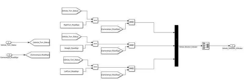
- Keep this requirement as a separate subsystem. Inputs to this requirement are a local signal from requirement 1 (Signal Name: Vehicle_Turn_Status) & an input signal from the camera (Signal Name: CameraInput_RoadSign), which confirms the occurrence of a road sign.
- Signal Vehicle_Turn_Status is compared against calibration values (Calibration Values: RightTurn_RoadSign, LeftTurn_RoadSign, Straight_RoadSign), if each of them is found equal, then each of the three corresponding output is compared against the camera input signal,
- Using a logical operator block, only one among them is finally given as an output signal (Signal Name: Vehicle_Direction_
Indicator). - Mux output is given to the signal conversion block to convert datatype of signal.
2. Tag the requirements to the simulink model; tagging requirement 1 & requirement 2 to their corresponding subsystems is fine.
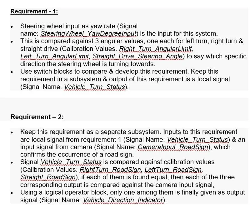
- Create a word file shown above containing details of both requirements and save this file in the same folder of your MATLAB model.
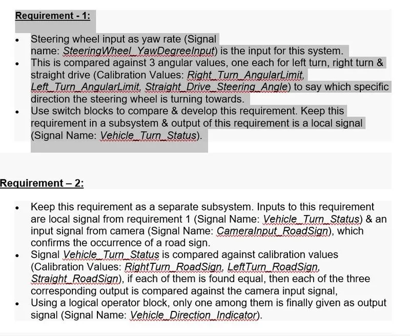
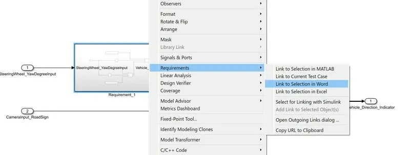
- Select the desired requirement in the file shown above and minimise the word file, Right click on subsystem whose tagging is to be done -> Requirements -> Link to selection in Word.
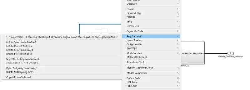
- As we can see above in requirement,Tagging is done for selected subsystem.when we click on that the same word file will open what we created for their requirements.
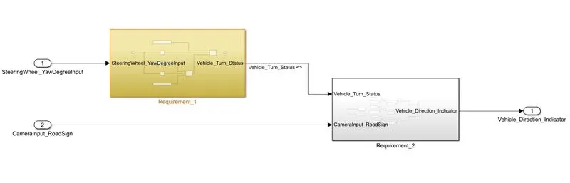
- Tagging will be done and by selecting subsystems it will appear with a coloured background shown above.
3. MBD compliant changes, Data Dictionary creation,S_Function & code generation is an added advantage, and that is not scope of this project.
(a) MBD compliant changes:-
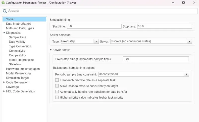
- Click on Modelling -> Model settings -> Solver
- In solver selection -> Type: Fixed-step and Solver: discrete (no continuous states)
- Under Solver details set Fixed step size: 0.01
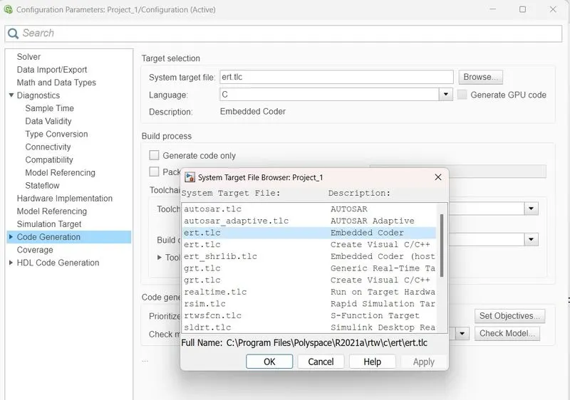
- In code generation -> Browse system target file for Embedded coder
- Apply and OK
(b) Data Dictionary creation:-
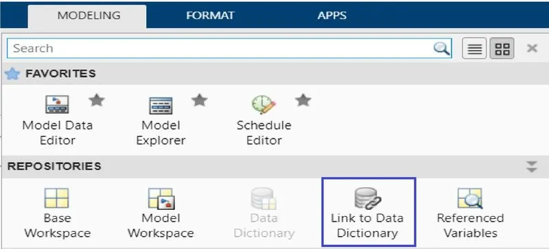
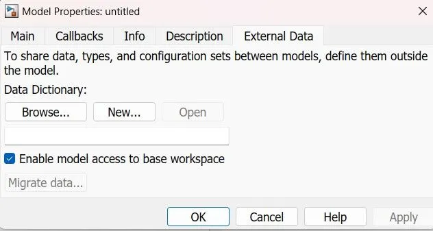
- In simulink model -> modelling -> design -> Link to Data Dictionary
- Window of model properties will pop up -> New -> Create a file name -> Apply OK -> Symbol will appear on the left bottom side shown above.
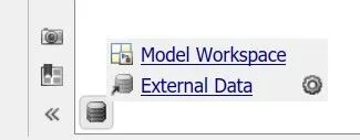
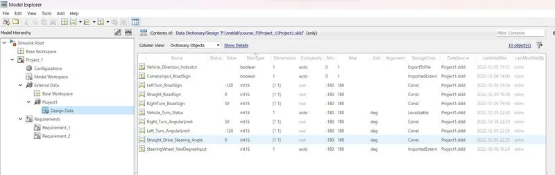
- Click on External Data and new window will pop up with a file name written on left side, selecting that will show down a object with "Design data"
- To add any signal click on Simulink Signal and for adding any constant click on Simulink Parameter.
- Above is shown the list of required signals and parameters to be used in this project.
(c) Creation of S block and code generation:-
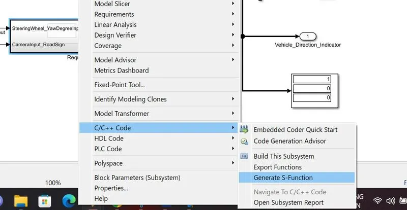
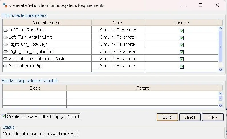
- To create S block -> Right click on subsystem -> C/C++ code -> Generate S function
- New window will appear -> Tick mark the block of SIL at bottom and then select Build option.
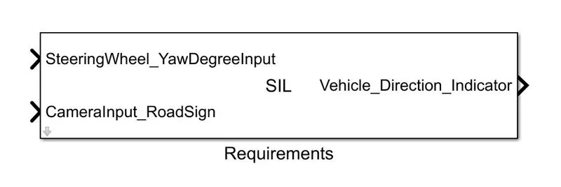
- A model file of S block will be created, which is shown below.

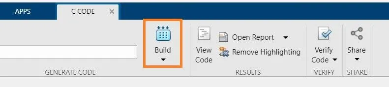
- To generate the code on Title bar -> Apps -> Embedded coder -> Build
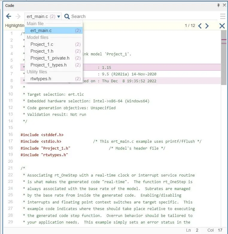
- Multiple code will be generated with extension of .c and .h files. Above is shown the list of generated codes.
4. Model Advisor:-
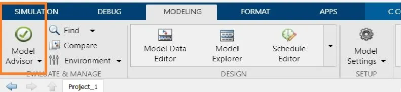
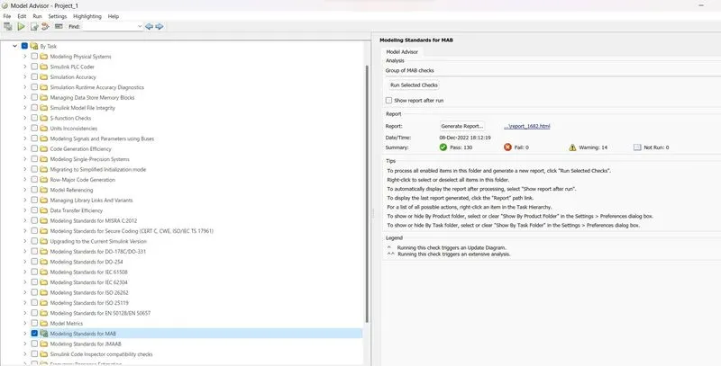
- On Title bar -> Modelling -> Model advisor -> Window with model name will appear Click OK -> New window will appear having options of By product and By Task
- Tick mark the following options shown Above and run the model advisor.
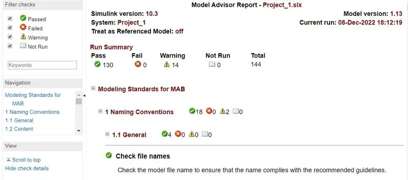
- The report generated by this model is supposed to have warnings less than 15.To reduce warnings, go through the report and solve the possible warnings and generate the report again.
- RESULTS:-
- RIGHT TURN:-
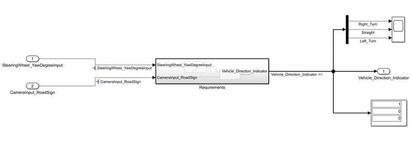
- Here,we are running our simulation by giving the value of Steeringwheel input as '23'.
- So,we can see the result in display as '1 0 0'.It means our vehicle is taking right turn.
- STRAIGHT:-
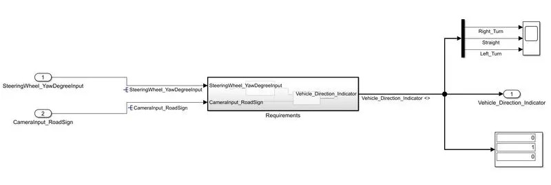
- Here,we are running our simulation by giving the value of Steeringwheel input as '0'.
- So,we can see the result in display as '0 1 0'.It means our vehicle is not taking any turn.
- LIGHT TURN:-
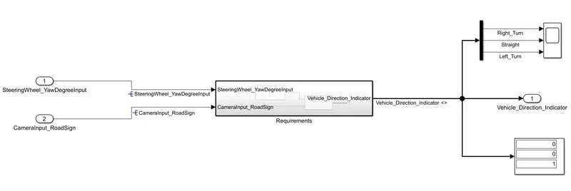
- Here,we are running our simulation by giving the value of Steeringwheel input as '-52'.
- So,we can see the result in display as '0 0 1'.It means our vehicle is taking left turn.
- CONCLUSION:-
- Hence,we created a system that detemines the direction of our vehicle by giving the camara and steeringwheel as input.