Week - 4
(1)AIM:-Implement control logic of a “washing machine” using Stateflow as per given sequence:
- If the power supply is available, the system gets activated
- If the Water supply is not available, stop the process & indicate through LED
- Soaking time should be 200s followed by Washing time of 100s.
- Then rinsing happens for next 20s & dryer runs for 50s
After all the processes have completed turn on the finished LED
- STATEFLOW:-
- It can used for graphical representation of a machine consisting of states,conditions and transitions.
- SIMULINK MODEL:-
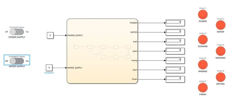
- As Shown in above model,we are using chart block for graphical representation of given condition for running the washing machine.
- Slider switches are used for trigger the power and water inputs by connecting with the constant blocks to provide the condition by toggling the swithes.
- Displays are used for give output about the whole process of the washing machine.
- Lamps are used for indication of the various state of the machine.
- CONTROL LOGIC:-
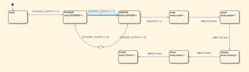
- Here is the control logic of the washing machine under given conditions.
- In the state flow chart,we first apply the condition for motor on by writing [POWER_SUPPLY==1].If it is not avaliable then the process is terminated by given condition [POWER_SUPPLY==0].If it is on than go to next step.
- We apply the condition [WATER_SUPPLY==1] for checking the availability of water.if not then the process is terminated by given the condition [WATER_SUPPLY==0].if it is on than go to next step.
- After power supply is on and Water is avaliable than soaking the clothes for next 200 sec by writing the condition after(200,sec).
- The motor runs forward and backward direction to wash the clothes for next 100 sec by writing the condition after(100,sec).
- After washing,rinsing is going to start for next 20 sec and dryer is used for 50 sec to dry the clothes by writing the conditions after(20,sec),after(50,sec).
- after all process are done the finish lamp is glow and terminated the process.
- OBSERVATION:-
- POWER:-
- Here power=off and water=0ff
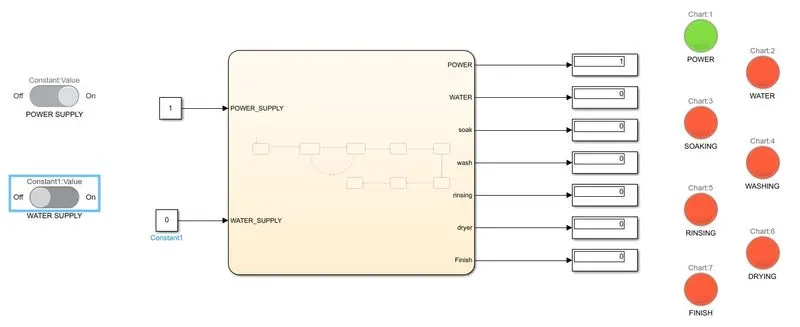
- power=on and water=off.
- SOAKING:-
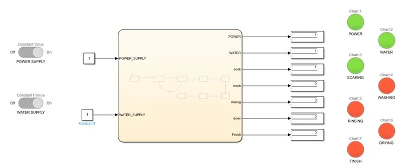
- Power=on,water=on,soak=on,t=10 sec
- WASHING:-
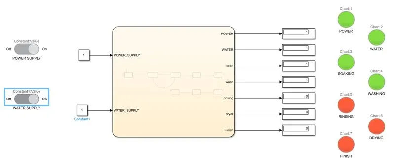
- Power=on,water=on,wash=on,t=230 sec
- RINSING:-
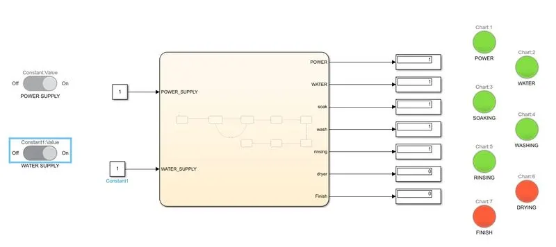
- Power=on,water=on,Rinse=on,t=330 sec
- DRYING:-
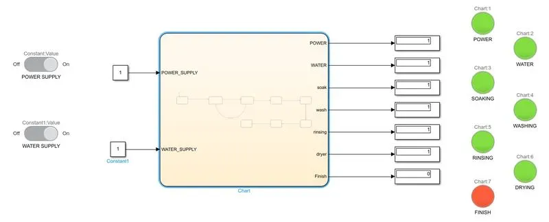
- Power=on,water=on,dry=on,t=350sec
- FINISH:-
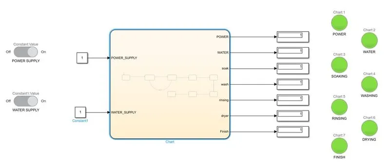
- Power=on,water=on,finish=on,t=450 sec
- So , these all are the states of the washing machine while it is running.and also we can get washing machine states at which it is currently working by using lamp indicator.
- CONCLUSION:-
We conclude that by using chart block we can easily built any of the machine working states for any time intervals.
(2)AIM:- Make a Simulink chart for the “Gear shift” logic as per below conditions:
Speed Range(kmph) Gear
0 to 15 1
16 to 25 2
26 to 40 3
41 to 60 4
Above 61 5
Give speed input while the simulation is running & display the gear number.
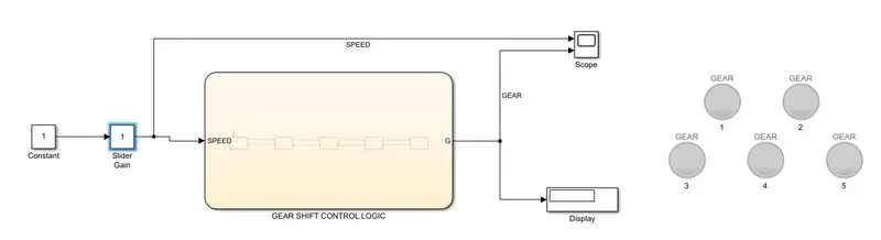
- SIMULINK MODEL:-
- SIMULINK MODEL DESCRIPATION:-
- As shown in above model, we are using chart block for gear shift logic for given condition.
- Constant block is use to give input to the chart block through slider gain which is nothing but a one kind of throttle.we can increase or decrease the value of constant block while simulation is running.
- Scope and display are used for give output about gear shift at given input speed to the chart block.
- Lamps are used for give indication about the gear at which our control logic works.
- CONTROL LOGIC:-

- As shown in above logic,we are putting some condition which given in the question.
- If our vehicle speed is between 0 to 15 than gear 1 will be apply.
- If our vehicle speed is goes above 15 than gear 2 will be apply by writing the condition [SPEED>15].if this condition is true than go to next state oherwise go to previous state.
- Similarly for GEAR3,GEAR4, and GEAR5,We written the conditon respectively [SPEED>25],[SPEED>40],[SPEED>60].If these conditon are true than it wiil go to next state oherwise go to previous state.
- OBSERVATION:-
- GEAR 1:-
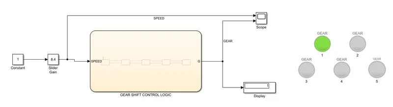
- As shown in above,our vehicle speed is between 0 to 15 than gear 1 is shown by display and lamp.
- GEAR 2:-
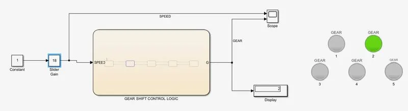
- As shown in above,our vehicle speed is between 16 to 25 than gear 2 is shown by display and lamp.
- GEAR 3:-
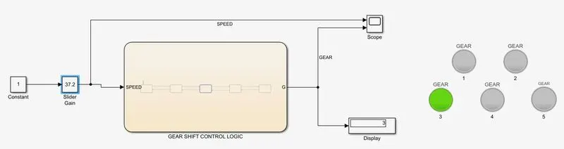
- As shown in above,our vehicle speed is between 26 to 40 than gear 3 is shown by display and lamp.
- GEAR 4:-
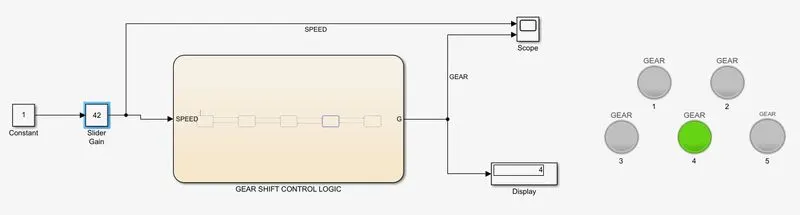
- As shown in above,our vehicle speed is between 40 to 60 than gear 4 is shown by display and lamp.
- GEAR 5:-
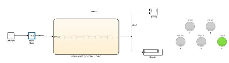
- As shown in above,our vehicle speed is above 61 than gear 5 is shown by display and lamp.
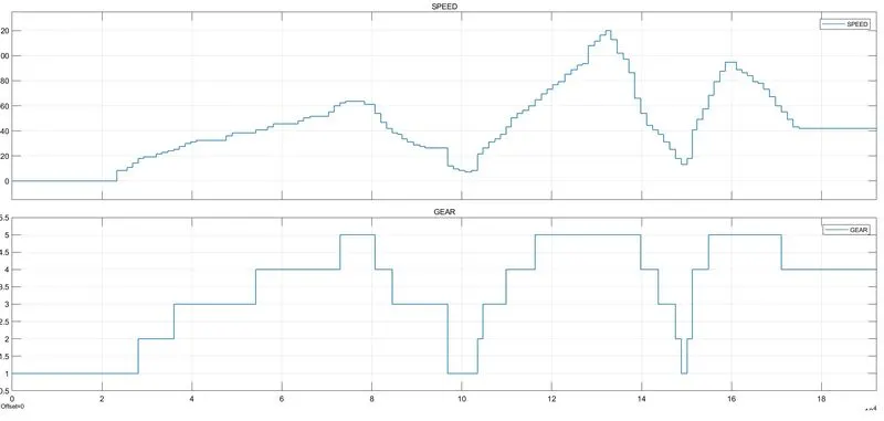
- So,we are running our simulation for infinite time and observe the scope about gear shifting by changing the value of speed using slider gain.
- From above scope, it is clear that our gear is shifting with changing the speed by user.
- CONCLUSION:-
By using slider gain we can easily increase and decrease the speed while simulation is running and observe gear number at display as well as through lamp.