Week-7 Challenge: DC Motor Control
1. A. Explain a MATLAB demo model named ‘Speed control of a DC motor using BJT H-bridge’.
B. Comment on the armature current shoot-up from the scope results.
C.Refer to the help section of ‘The Four-Quadrant Chopper DC Drive (DC7) block’. Compare it with the H-bridge model.
Ans.
A. Explain a MATLAB demo model named ‘Speed control of a DC motor using BJT H-bridge’.
Ans.
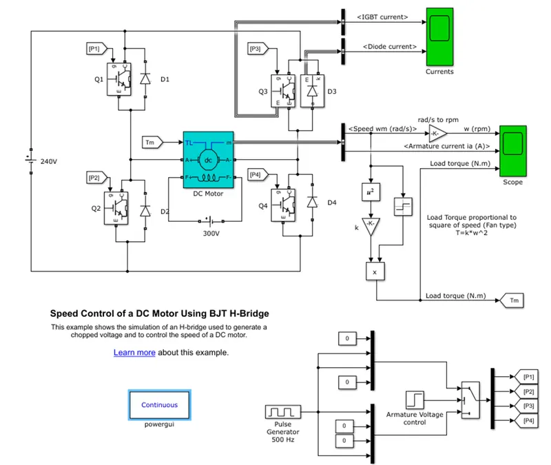
Here below model image is provided.
Simulink model :-
Here used block :-
DC motor, IGBT, diode, DC voltage source, pulse generator, step function, switch, scope, mux, powergui for configuration of power electronics device, gain, constant, multiplier, math function.
Model description:-
- This model is used 4 IGBT and 4 Diode, step time is given in armature voltage control and duty cycle is given in pulse generator.
- Here we show that DC motor has 6 different port F+, F-, A+, A-, M, T.
- F is field current here we give field current separately because motor is use separately excited DC motor.
- Here for power switching we used pulse generator to operate IGBT and this is pair of 1 &4 and 2 & 3 operated in pair.
- Here we can see IGBT connection with parallel of diode because of safety purpose of that power switch.
- These IGBT has three port B, E, C. these b is base voltage which decide the passing through voltage.
- These IGBT is connected with 240 volt DC to operated DC motor and IGBT port E is connected with A+ and A- to excited the armature.
- In DC motor block TL port is input torque this can be various or constant but here we give constant torque.
- In DC motor block port m is output of various data like speed, armature current etc .
Now we talking about working
- Here given voltage to armature is 0 to 240v when pulse is varies 0 to 100%.
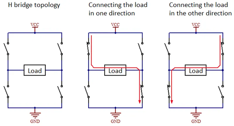
- Here H-bridge circuit is used for rotating in forward direction and reverse direction the DC motor.
- Here we use 4 BJT(IGBT) and 4 diode to perform the operation.
- Here if path is Q1 & Q4 is forward direction because Q1 and Q4 is gives positive voltage to motor and diode D2 and D3 is free wheeling diode.
- if voltage path is Q2 & Q3 is reverse direction because Q2 and Q3 is gives negative voltage to motor and diode D2 and D3 is free wheeling diode.
- Here below image is shows for forward and reverse direction.
Now we discuss about the result of model.
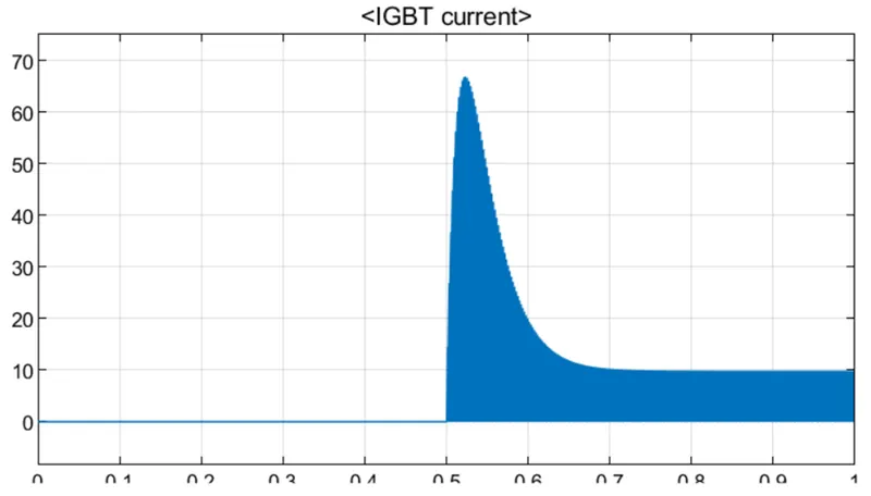
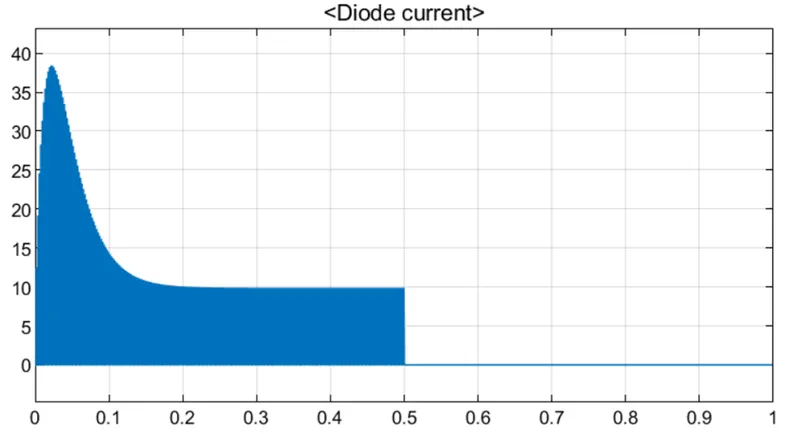
In above image first 0 to 0.5 sec diode D3 is passing through current and 0.5 to 1 sec IGBT passing through current.
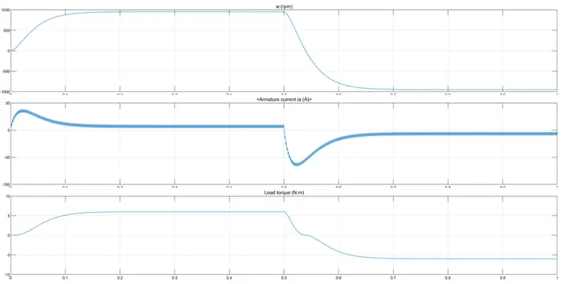
Here above image in starting sudden peak current and at the reverse direction time current is peak in negative direction.
B. Comment on the armature current shoot-up from the scope results.
Ans.
Here we discuss about armature current.
In above model value of armature current is depend on the pulse generator duty cycle. Here default value is given 75%.
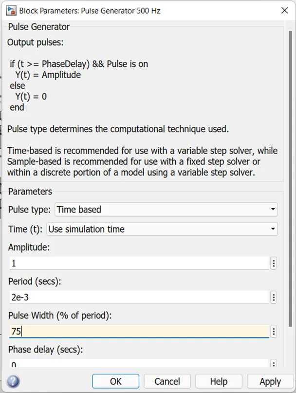
Below gives image is result of armature current at 75% duty cycle of pulse generator.

Here we can see this the current is required high when the motor is starting because of starting torque is very high so current is also required more in starting.
Here also in at time 0.5 sec we can see that current is change because the motor rotation direction is change and therefore Q1 & Q4 is operated so here current goes in negative direction because of reverse direction.
And this depend on duty cycle also which we can compare with in below image which duty cycle is change 75% to 50% .
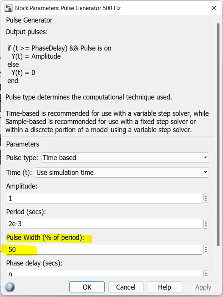
Now we can see this effect in below image.

Here we see that current value change at direction time is less then compare to duty cycle 75% and because of low value of current effect of torque and direction is not more see compare to high current value.
C. Refer to the help section of ‘The Four-Quadrant Chopper DC Drive (DC7) block’. Compare it with the H-bridge model.
Ans.
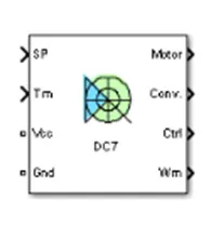
In matlab help section DC-7 four quadrant chopper 200 HP DC drive and we get this model.
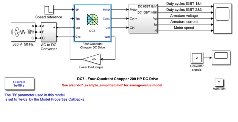
In above four quadrant chopper DC drive DC7 block model, 3 phase voltage source and AC to DC convertor rectifier bridge and braking chopper is added to four quadrant dc chopper dc7 block. The armature voltage is provided by IGBT converter controlled by two PI regulator.
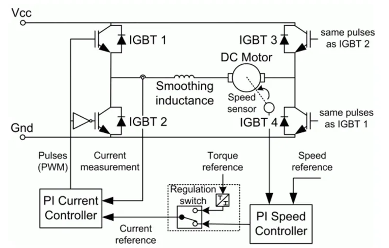
Now from this model we discuss only four quadrant chopper DC chopper which image is below shows.
The four-quadrant chopper:-
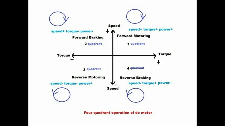
In four quadrant chopper can operated in all four quadrant chopper. Power can flow either source to load or load to source.
The four quadrant operation:-
Quadrant 1 (forward motoring)
CH1 turned on
When the CH 1 turned on, CH1 and CH4 conduct and output voltage v0 and output current i. these both are positive and power flow source to load, inductor store the energy and motor rotate in forward direction so it’s called forward motoring.
CH 1 turned off
When the CH1 turned off , CH4 and D2 conduct , positive current free whiling through CH4 and D2 motor rotate forward direction and output voltage zero and output current is i. these value of current is positive and inductor is release the energy.
Quadrant 2(forward regenerative braking)
CH2 turned on
Assume that motor running in forward direction. Here CH2 is operated so CH2 and D4 is conduct, output voltage is v0 and current is in negative directive which produce Eb. This behaves like generator and inductor store energy.
CH2 turned off
CH2 is off then D1 and D4 is conduct so voltage v0 positive and current is negative and inductor release energy which is flow load to source direction and power fed from load so this is called forward regenative braking.
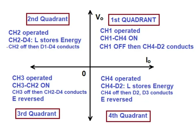
Quadrant 3(reverse motoring)
CH3 turned on
Polarity od back efm is must be in reverse. Here CH3 is on so CH3 and CH2 is conduct output voltage is negative and current is negative, power is flow source to load and inductor is store energy and motor rotate in reverse direction so we called reverse motoring.
Ch3 turned off
CH3 is turned off so CH2 and D4 is conduct and negative current free whiling through CH2 and D4. Current is negative and voltage is zero, inductor is release energy and motor still running in negative direction.
Quadrant 4 (reverse regenerative braking)
CH4 turned on
Polarity od back emf is must be in reverse. Let us assume that motor rotate reverse direction. CH4 is operated, CH4 and D2 is conducted, output voltage is zero and current is positive so Eb is positive. So that machine behaves generator and inductor store the energy.
CH4 turned off
When CH4 turned off then D2 and D3 is conduct. Load voltage is negative but current is positive and power fed back to source. So that called as reverse regenerative braking.
Comparison of four quadrant chopper Vs H- bridge model
- Four quadrant chopper can operate in four quadrant forward motoring, reverse motoring, forward regenerative braking, reverse regenerative braking.where H- bridge model is operate only in two quadrant forward motoring and reverse motoring.
- Four quadrant chopper can regenerative braking features are available where H-bridge model does not allow this feature.
- Higher efficiency in four quadrant chopper compare to H-bridge and less maintenance required in four quadrant chopper.
- Four quadrant chopper is used in numerous application in power switching device and electronic device where H-bridge circuit is mostly used in robotics application for DC motor reverse and forward direction.
- Develop a 2-quadrant chopper using simulink & explain the working of the same with the relevant results. (Refer to article - Multiquadrant operation of motor)
Ans.
Two quadrant chopper known as C-type chopper. Type-C chopper is obtaining from type-A and type-B chopper in parallel. We will always on voltage is positive v0 and free whiling diode FD is presented across load.
In two quadrant chopper voltage is always positive and may be positive or negative current. In first quadrant voltage and current both are positive so motor rotate positive direction so called forward motoring.
second quadrant voltage remains positive and current is negative direction so that called as regenerative braking.
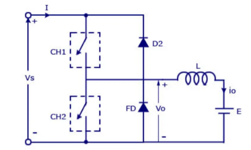
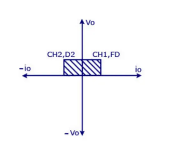
Now we talking about the model of two quadrant DC chopper:-
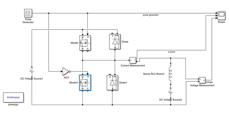
Here we used two IGBT and two diode block to perform the two quadrant DC chopper.
Pulse generator give pulse to mosfet for operating as switching and we can operate the this chopper in first and second quadrant.
We get results from model is below image is shown.
RESULT:-
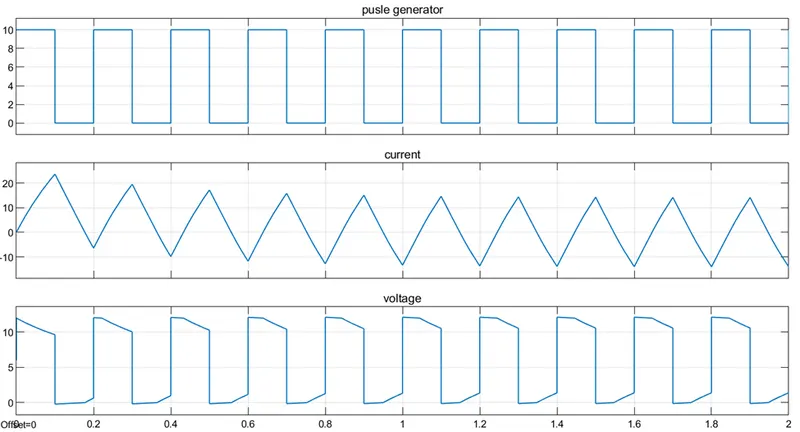
In the result we can see that our voltage value is not going to negative, it is zero or above.
Here current value is may varies negative or positive but positive in first quadrant when CH1 or mosfet(which is shown in model) is operated and negative when second quadrant CH2 or mosfet1(which is shown in model) is operated.
- Explain in a brief about operation of BLDC motor.
Ans.
Motor is converts supplied electrical energy into mechanical energy. Various types of motors are in common use. Among these, brushless DC motors feature high efficiency and excellent controllability, and widely used in many applications. The BLDC motor has power-saving advantages relative to other motor types.
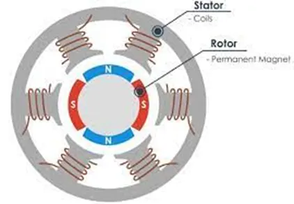
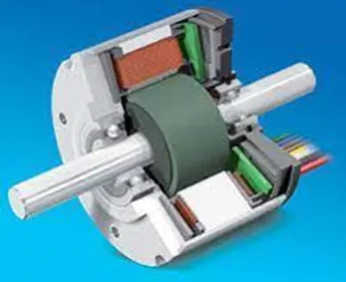
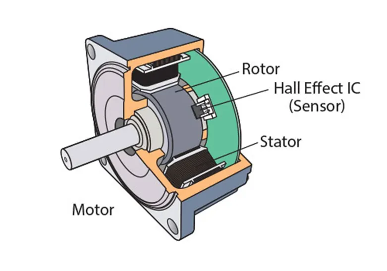
Below shows some image of BLDC motor.
CONSTRUCTION OF BLDC motor:-
BLDC motor understand first construction. In BLDC motor construction in rotor permanent magnet is available since here permanent magnet is provided there is no need to current so we can eliminated the brush and stator is field winding coil pole which excited by DC current and magnetic flux and control the motor speed and torque.
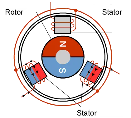
Below shows working of image of BLDC motor.
WORKING OF BLDC motor:-
Working principle of BLDC motor is Lorentz force law which is state that whenever a current carrying conductor placed in a magnetic field it experiences a force. As a consequence of reaction force, the magnet will experience an equal and opposite force.
When the stator coil get supply source of dc volt then it become electromagnet and start producing field in air gap. Now situation is electromagnet and permanent magnet experience the force between this stator and rotor and rotor rotate continues.
The stator magnetic pole change by continues which is done by the DC drive. The pole change and rotor magnetic pole is attractive and repulsive one by one and rotor rotate at some torque which is depend on the flux density and current.
Based on the current field flux is generate and decide the value of speed and torque, it depend also in number of pole and frequency.
Advantage of BLDC motor:-
BLDC motor give high power to weight ratio.
We can control on torque and speed instantaneous control.
We get high efficiency, low maintenance because of brush less, high speed.