Week - 4
- Implement control logic of a “washing machine” using Stateflow as per given sequence:
- If the power supply is available, the system gets activated
- If the Water supply is not available, stop the process & indicate through LED
- Soaking time should be 200s followed by Washing time of 100s.
- Then rinsing happens for next 20s & dryer runs for 50s
After all the processes have completed turn on the finished LED
Ans.
Block used for this problem:- chart, constant, display, button, lamp.
Model image is below provide.
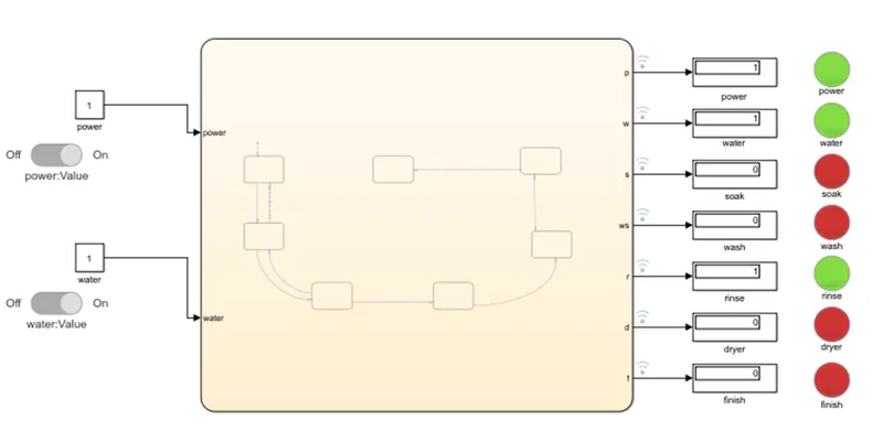
For solve this problem understand the washing machine basic concept is necessary.
Normally washing machine is start with two condition full-fill that first is power supply and water available.
After that based on set programme it’s work. Normally first soaking, washing, rinse, dryer with some heat and finish.
Now we solve this problem first take chart from stateflow.
chart image below provide.
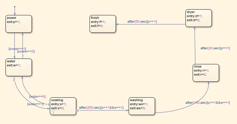
In this chart make flow chart like above. For this take state and connect it with our condition.
Condition is power and water available and previous state time delay is end.
Here we require seven state which list in below.
- Power
- Water
- Soaking
- Washing
- Rinse
- Dryer
- Finish
All state has their on condition which is shows in above image and it’s all perform specific time delay.
Based on time all state perform one by one it may not perform at time two state.
Now below shows result image.
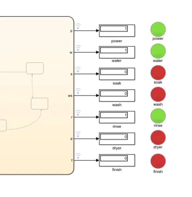
In this result we can see that our rinse state is perform it’s task with green lamp.
As here shows one state like that all state is perform one by one their task. In between our water not available then stop the process and it’s show indication in red light in water lamp.
For more simulation model link provide below.
matlab version is 2018a.
https://drive.google.com/file/d/1-ld7fBUJrcNIi1FvhcDbz7XulxtDfWUT/view?usp=sharing
if linknot work then below atteched file.
2. Make a Simulink chart for the “Gear shift” logic as per below conditions:
Speed Range(kmph) Gear
0 to 15 1
16 to 25 2
26 to 40 3
41 to 60 4
Above 61 5
Give speed input while the simulation is running & display the gear number.
Ans.
Block used in this model:- signal builder, chart, display.
Model image below provide.
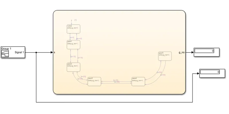
For this problem first we required continuous speed for that we here used signal builder.
That speed give to the chart.
Chart image below provide.
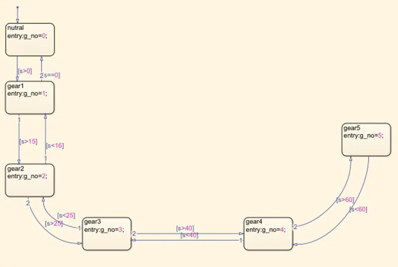
In this chart we can see that here give six state.
All state has own condition based on condition state perform it’s task.
First state is for ideal condition and rest of state is provide for gear number. Gear state shift based on the it’s state condition which is speed limit.
Now below shows result image.
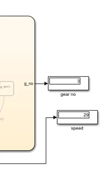
In above image we can see that gear no. =3 and our speed= 29 it’s prove that our model is right and full fill our condition of speed based.
For more simulation model link provide below.
matlab version 2018a
https://drive.google.com/file/d/1sszOE4b08I4HrByO5ucU-EhG98zQ7yYY/view?usp=sharing
if link not work below file atteched.