Project 1 - Controlling a DC motor using PWM and monitoring its Running status
Overview of the Project:
Implement a system on the simulator for controlling a DC motor using L293 motor driver, monitor its status and print the running status of motor on the LCD Display.
Ans.
code for this project.
#include <avr/io.h>
#define F_CPU 16000000L
#include<util/delay.h>

#define RS_LOW PORTB &= ~(1<<2); //DEFINE BIT FOR RS_LOW
#define RS_HIGH PORTB |=(1<<2); //DEFINE BIT FOR RS_HIGH
#define EN_LOW PORTB &= ~(1<<3);//DEFINE BIT FOR EN_LOW
#define EN_HIGH PORTB |=(1<<3);//DEFINE BIT FOR EN_HIGH
void motor_direction(int status, int delay) //PROGRAM FOR MOTOR DIRECTION
{
	OCR0A = delay;  //TAKE DELAY
	PORTB = 0x40; //ENABLE L293 CHIP
	if(status == 0) //for off
	{
		PORTB &= ~(1<<0);
		PORTB &= ~(1<<1);
	}
	if(status == 1) //for forward direction
	{
		PORTB |= (1<<0);
		PORTB &= ~(1<<1);
	}
	if(status == -1)   //for reverse direction
	{
		PORTB &= ~(1<<0);
		PORTB |= (1<<1);
	}
}
void motor_timer0() //MOTOR TIMER
{
	DDRB = 0xff; //MAKE PORT D AS OUTPUTP;
	TCCR0A = 0b00000011; // select mode fast PWM
	TCCR0B = 0b00000001; // set prescaler
	OCR0A = 68;
	motor_direction(0, 150);
}
void lcd_cmd(unsigned char cmd)
{
	PORTD = cmd;
	RS_LOW; //FOR SET TO COMMAND MODE
	EN_LOW; //CREATE CLOCK SIGNAL
	_delay_ms(5);
	EN_HIGH;
}
void lcd_data(unsigned char data)
{
	PORTD = data;
	RS_HIGH; //SET TO DATA
	EN_LOW; // CREATE CLOCK SIGNAL
	_delay_ms(5);
	EN_HIGH;
}
void lcd_init()
{
	lcd_cmd(0x38); _delay_ms(5);
	lcd_cmd(0x38); _delay_ms(5);
	lcd_cmd(0x38); _delay_ms(5);
	lcd_cmd(0x38); _delay_ms(5);
	lcd_cmd(0x0c); _delay_ms(5);
	lcd_cmd(0x01); _delay_ms(5);
	lcd_cmd(0x06); _delay_ms(5);
	lcd_cmd(0x80); _delay_ms(5);
}
void cursor_position(char x, char y)//SET THE CURSOR POINT
{
	if((x < 1 | x > 2)||(y < 1 | y > 16))
	{
		x=1;
		y=1;
	}
	if(x==1)
	{
		lcd_cmd(0x7f+y);
	}
	else
	{
		lcd_cmd(0xbf+y);
	}
}
void lcd_out(char a, char b, char *str)//PRINT IN LCD
{
	cursor_position(a,b);
	while(*str)
	{
		lcd_data(*str);
		str++;
	}
}

int main(void)
{
	DDRC = 0x00; //MAKE PORT C PIN 1,0 AS INPUT
	PORTC = 0xff ; // ACTIVATE THE PULL UP RESISTOR
	lcd_init();
	motor_timer0();
	char g[20] = "motor stop";
	lcd_out(1,1, &g);
	_delay_ms(500);
	while(1)
	{
		if((PINC & (0x01)) == 0)
		{
			motor_direction(1,80); // MOTOR DIRECTION CALL
			lcd_cmd(0x01); //CLEAR SCREEN
			lcd_cmd(0x01);
			char d[20] = "rotate anti_cw"; //SEND TO LCD
			lcd_out(1,1, &d);
			_delay_ms(500);
		}
		if((PINC & (0x02)) ==0)
		{
			motor_direction(-1,80); //MOTOR DIRECTION CALL
			lcd_cmd(0x01); //CLEAR SCREEN
			lcd_cmd(0x01);
			char c[20] ="rotate cw"; //SEND TO LCD
			lcd_out(1,1,&c);
			_delay_ms(500);
		}
	}
}
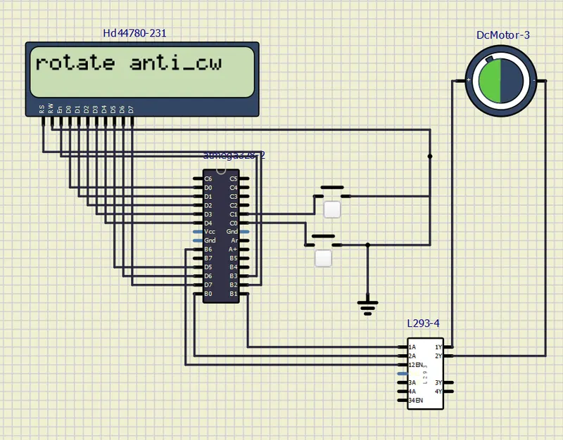
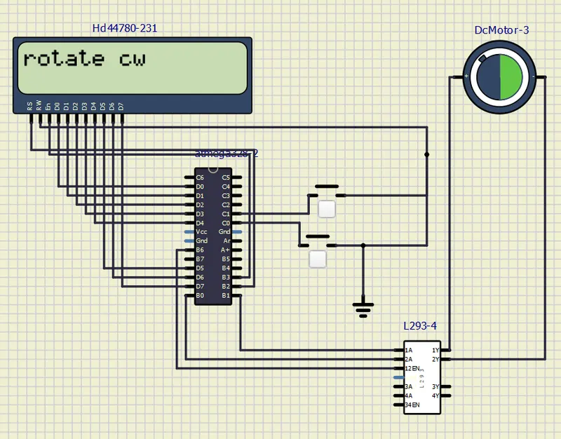
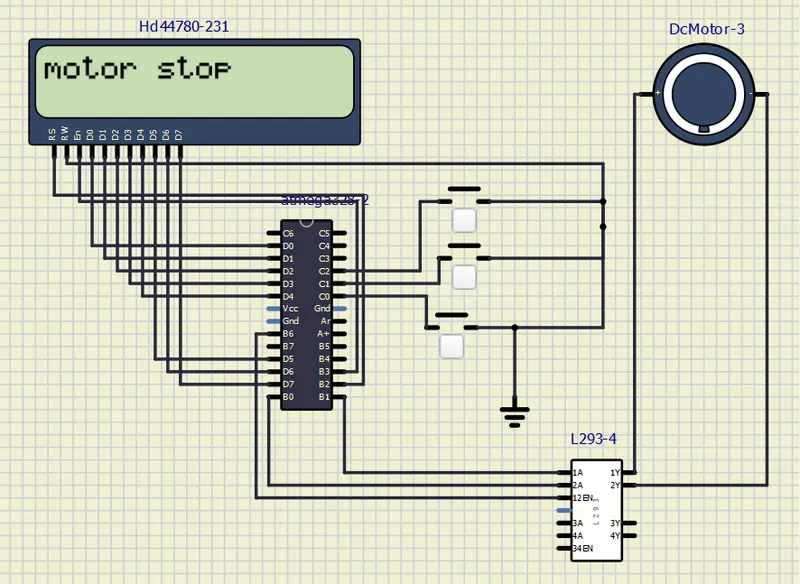
circuit diagram of project.
rotate in anti clockwise when press third button.
rotate in clockwise when press second button.
motor is stop. wheen press first button.
all the require file is below atteched.