Week -2
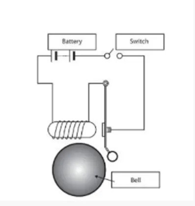
- Make a Simulink model of Doorbell using solenoidblock with the following details:
In the above arrangement, when the switch is closed the electromagnet receives electrical power from the battery and pulls the metal arm to hit the bell producing sound.
Create a situation where the switch is closed for 2 seconds and then released. Observe the physical movement of the plunger.
Assume remaining parameters.
Ans.
Block used in this model :- pulse generator , Simulink to PS converter, PS to Simulink converter, switch, DC source voltage, solenoid, ideal translation motion sensor, electrical reference, mechanical translation reference, solver configuration.
Model link is provide below.
i am uploading google drive link of matlab file(model file), i am using matlab2018a version.
- link for model file (version 2018r) : https://drive.google.com/file/d/1vTVrPxgFi9jGCiVjqr5O8rEj2Mk1FW0C/view?usp=sharing
if above link is not work then below model pdf atteched.
-To solve this problem first take DC voltage source and connect with switch and switch connect to the with solenoid positive.
- Solenoid R,C port use to see movement of plunger. Here the way to connect ideal translation motion sensor.
- R port connect with sensor in this I see that our result is get but in negative direction means plunger is going opposite side. C port is connect with mechanical translation reference.
- link for result pdf :- https://drive.google.com/file/d/18ZT-R9LY1GpNCPv6vomVmDdI4iiNU5Zj/view?usp=sharing
if above link is not work then below pdf atteched.
Observation from result
- When the switch press(operated) at that time solenoid produce electromagnetic force and plunger attract to that electromagnetic force going opposite direction so we can see that movement in result and after 2sec switch release at that time plunger go it’s start position or zero position(home position).
- when we give rated voltage of solenoid then plunger movement is accurate as with voltage value.
- When we give below the rated voltage then plunger make some delay in movement.
- When we give above rated voltage then plunger is more going toward the bell. All of three case is shows in below result PDF or above link.
- Use a thermistor to sense the temperature of a heater & turn on or turn off the fan as per the below conditions:
Temperature source: 20 °C from 0 to 10 seconds, 27 °C from 10 to 30 seconds, 23 °C from 30 to 50 seconds
Fan conditions: ON if the temperature above 25 °C, OFF otherwise
Ans.
Block used in this model :- Signal builder, Simulink to PS converter, temperature controller source, PTC thermistor, ideal temperature sensor, switch, DC voltage source, thermal reference, electrical reference, solver configuration, constant, scope, constant.
i am uploading google drive link of matlab file(model file), i am using matlab2018a version.
model link is below provided.
- link for moel file(version 2018r) : https://drive.google.com/file/d/1DTq77bo1JqKA2cXOTXO4whALKKFyAuDJ/view?usp=sharing
if above link is not work then below pdf atteched.
- To solve this problem first take thermistor connect with DC voltage source or battery.
- Thermistor have three port( A , +, - ). + and – used to voltage source. A is for change in temperature based on that resistance. Here we used negative co-efficient resistance so when temperature increase resistance is decrease.
- For temperature source we used a signal builder or Repeating sequence stair. Here we use signal builder because in this graph is visualize so error reduce. In the signal builder build the signal as we want in term of temperature in kelvin unit.
- Here I had use NTC thermistor. voltage is decrease as temperature raised so for fan ON/OFF we measure voltage across the thermistor and that is use for fan control.
- For fan ON\OFF first we measure the value of voltage at 298K temperature so that we can put this value to switch threshold value. Here we are measure voltage in negative value because of our thermistor is negative temperature coefficient so as temperature decrease resistance is decrease so voltage is also decrease. For this negative coefficient voltage measure value is also take in negative so we can easily trigger switch and fan is control ON/OFF.
- link for result pdf: https://drive.google.com/file/d/1DFmyfnthAxhIioqRvoAnR4QLgdDs4w-b/view?usp=sharing
if above link i not work then below pdf atteched.
- In this result we get negative voltage because here we use negative temperature coefficient so as temperature raise voltage decrease so that voltage we measure negative value so it’s convenient for fan control.
- In above result when temperature reach 298K and voltage is shows that above the switch threshold value so switch is operated and remaining time switch is off(fan).