Final Project: Design of an Electric Vehicle
Create a MATLAB model of electric car which uses a battery and a DC motor. Choose suitable blocks from Powertrain block set. Prepare a report about your model including following:
Objectives:
- System level configurations
- Model parameters
- Results
- Conclusion
Ans.
INTRODUCTION OF ELECTRIC VEHICLE :-
EVs are vehicles that are either partially or fully powered on electric power. Electric vehicles have low running costs as they have less moving parts for maintaining and also very environmentally friendly as they use little or no fossil fuels (petrol or diesel). While some EVs used lead acid or nickel metal hydride batteries, the standard for modern battery electric vehicles is now considered to be lithium ion batteries as they have a greater longevity and are excellent at retaining energy, with a self discharge rate of just 5% per month. Despite this improved efficiency, there are still challenges with these batteries as they can experience thermal runaway, which have, for example, caused fires or explosions in the Tesla model S, although efforts have been made to improve the safety of these batteries.
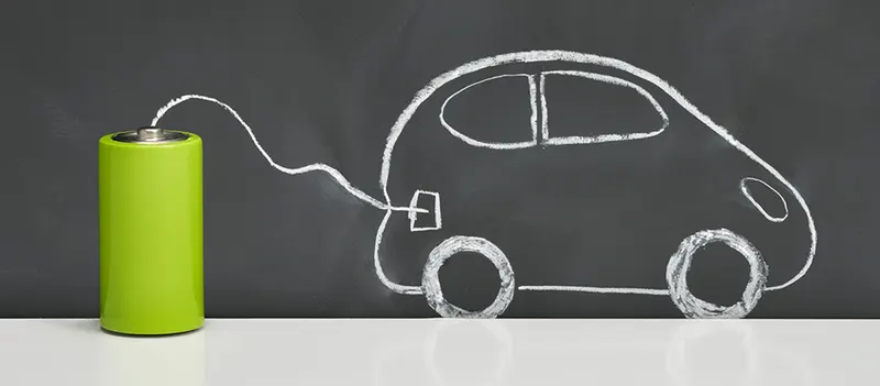
There are two types of electric vehicle battery electric vehicle and plug in hybrids.
Battery electric vehicle :-
This types of vehicles if we compare with conventional vehicle internal combustion engine in electric vehicles having less moving around 99% which needs maintenance which is one of the main advantage.
Plug in hybrid electric vehicle :-
Rather than relying solely on an electric motor, hybrid electric vehicles offer a mixture of battery and fossil fuel(petrol or diesel) power. This makes them better for travelling long distances as you can switch to traditional fuels rather than having to find charge points to top up the battery.
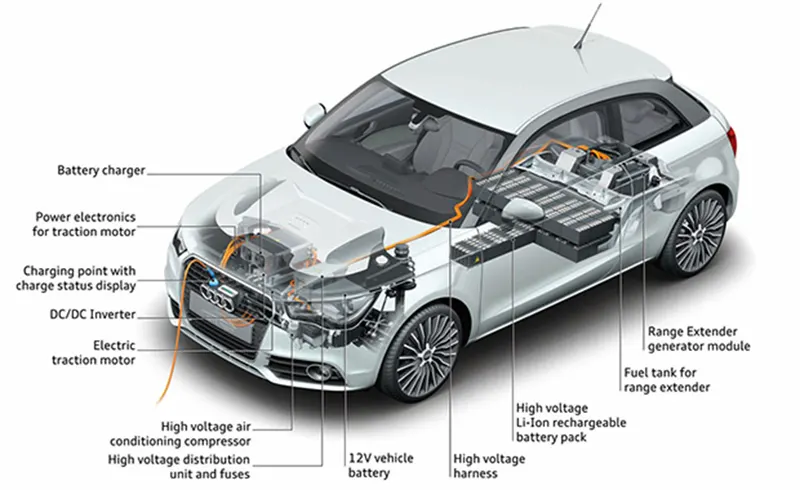
Electric car internal structure
SYSTEM LEVEL CONFIGURATION :-
To create model of electric car in MATLAB, first we divide in subsystem for easy to build the whole car and after that connect with as per requirement and design full electric vehicle model. For that We need block diagram for refernce to more clear about model.
In system level configuration of electric vehicle consists mainly:-
- Vehicle body
- Motor and controller
- Battery and power converter
- Drive cycle
From above block diagram we make electric vehicle model which similar to this block diagram which model image is below given.
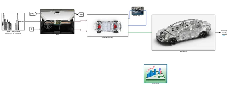
To more relate with real life we take one case here to design electric vehicle we take one real car which is TESLA MODEL 3 so based on this car parameter here we put all other parameter so we can compare that how accurate our model.
In the above model seen that there are many subsystem and now we understand that subsystem in more deeply.
MODEL PARAMETER (configuration and parameters):-
- Motor & controller :-
In this subsytem what we see of vehicle part is shows in below image.
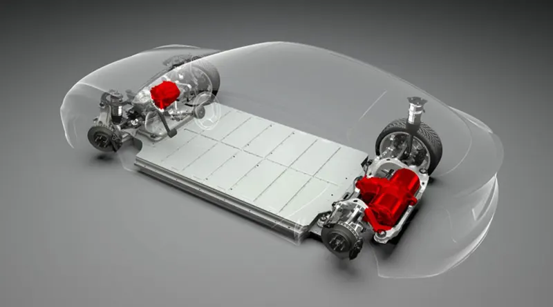
In above image red part is showing of motor and it’s controller or motor drive which is discuss in this subsystem and this image is tesla model 3.
The complete subsystem is below image shows in image.
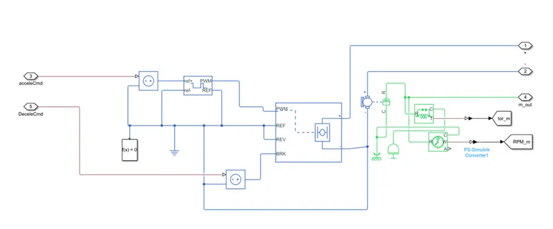
In this subsystem we use controlled PWM voltage, H-bridge, DC motor etc.
- Controlled PWM voltage:-
- This block is provide PWM to H—bridge as per requirement of H-bridge.
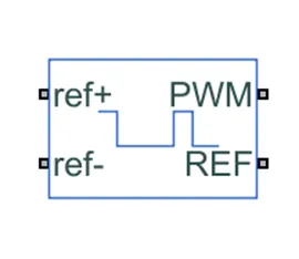
- PWM is pulse width modulate of electrical signal.
- REF is referance of zero for H-bridge
- Ref+ is positive referance voltage signal port.
- Ref- is negative referance voltage signal port.
- Parameter of this block is given in below image.
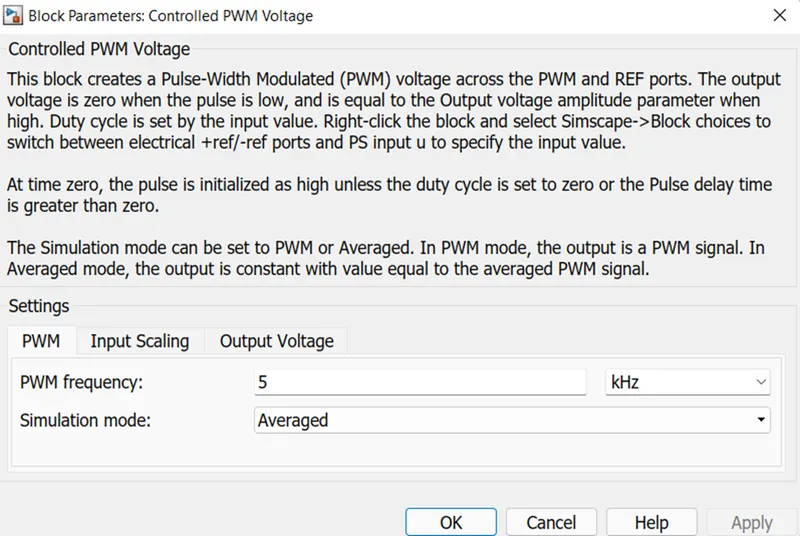
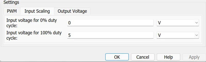
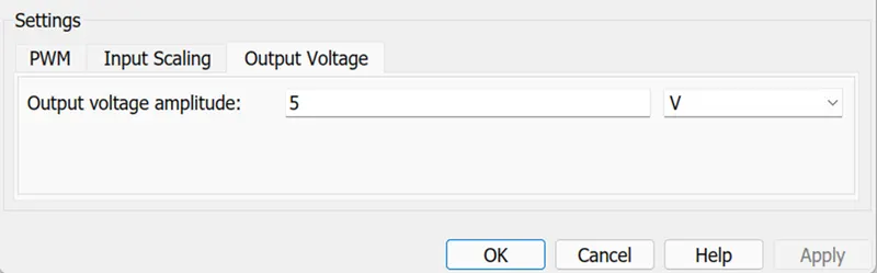
- In this parameter is we can see that set input the value of pulse voltage maximum and minimum and in output maximum value of voltage to give H-bridge which is based on H-bridge.
2. H-bridge:-
- This block is used as motor driver or controller for getting desire speed and torque in motor or we can say that this is heart of our model.
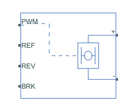
- The block can be driven by controller PWM voltage block in PWM or averaged
- In averaged mode PWM port voltage divided by PWM signal amplitude parameter defines ratio of on time to PWM period.
- In PWM mode motor is powered if PWM port voltage is avobe wnabled thresold voltage.
- REF is or referance input of PWM signal voltage.
- PWM connected with form pulse input for H-bridge.
- REV is reverse motion of motor which essentially means backwaard motion of vehicle.
- BRK is for braking pulse in H-bridge.
- Now we discuss about parameter which images are shows in below.
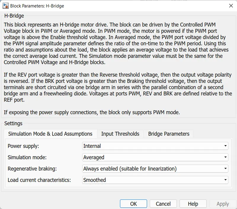
- In this power supply mode take internal because of if we selecting external then simulation time is required more than we expected so here we take internal power supply mode so the run time is less which is comfortable for us.
- And same things on simulation mode here take averaged rathe than PWM to overcome the simulation time length.
- Remaininng pparameter is default.
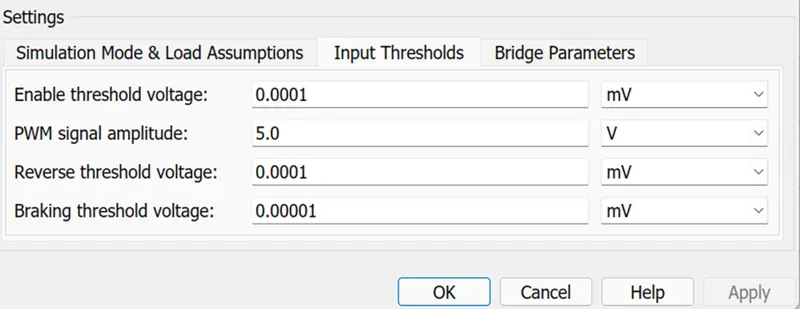
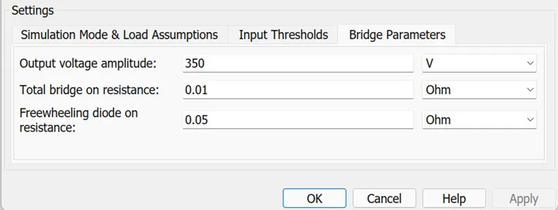
- This output voltage based on this TESLA MODEL 3 which has 350V battery output.
3. DC motor :-
- This block is electromechanical which is convert electrical energy to mechanical energy.
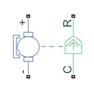
- Port + is for positive of electrical signal with motor positive terminal.
- Port – is for negative of electrical signal with motor negative terminal.
- Port R is a mechanical conserving port which is connected with outer shaft and which is help to transmission system.
- Port C is also mechanical conserving port which is connected with rotational refernce.
- In this block we can see two color which is green shows mechanical part and blue shows electrical part.
- Now we discuss about it’s parameter.
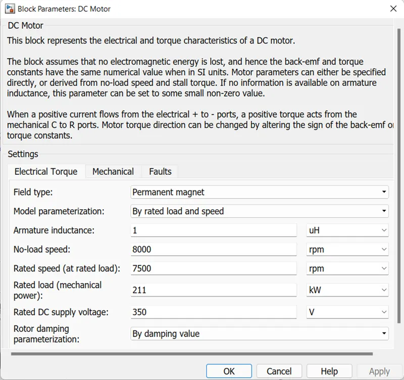
- Here take rated speed and rated DC supply voltage based on tesla model 3.
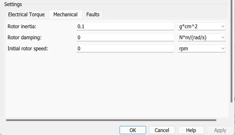
4. Other block:-
- Here we used solver configuration for electric blocks to solve parameter of physical network and define that it’s continoues or discrete.
- Electric referance block which is used to connected circuit with ground.
2. Vehicle body subsytem:-
- In the vehicle body subsystem below image is shows that what part is discuss in this subsystem.
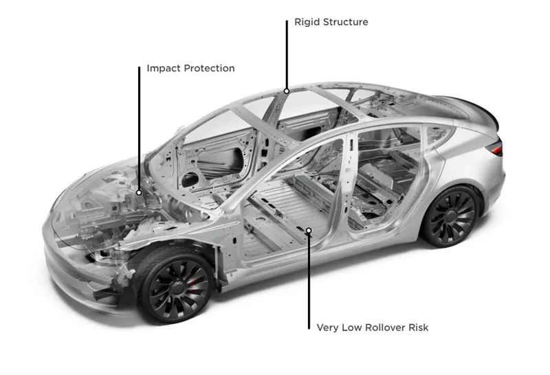
- In above image shows that curb and tire which is discuss in this subsystem.
- The complete subsytem is below image shows in image.
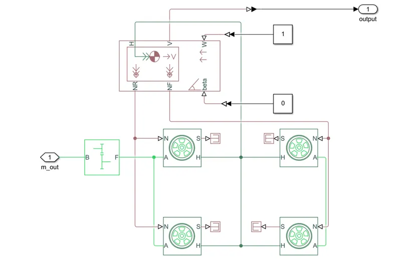
- In this subsytem we use vehicle body block, tire(magic formula) and simple gear ratio which is explain below with it’s parameters.
- Vehicle body:-
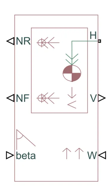
- This block is 2-axle and 4 wheel assembly connected with velocity body.
- The vehicle can have the same or a different number of wheels on each axle. For example, two wheels on the front axle and one wheel on the rear axle. The vehicle wheels are assumed identical in size. The vehicle can also have a center of gravity (CG) that is at or below the plane of travel.
- The block accounts for body mass, aerodynamic drag, road incline, and weight distribution between axles due to acceleration and road profile. Optionally include pitch and suspension dynamics. The vehicle does not move vertically relative to the ground.
- Now discuss on it’s port H is mechanical translation conversing port hub, Port V is output of total velocity of vehicle body. Port BETA is input road inclination angle, port W is input port represent headwind speed and NR and NF is output port of normal force of rear tire and front tire respectively in Newton.
- In this block geometric parameter is given for vehicle is as below shows.
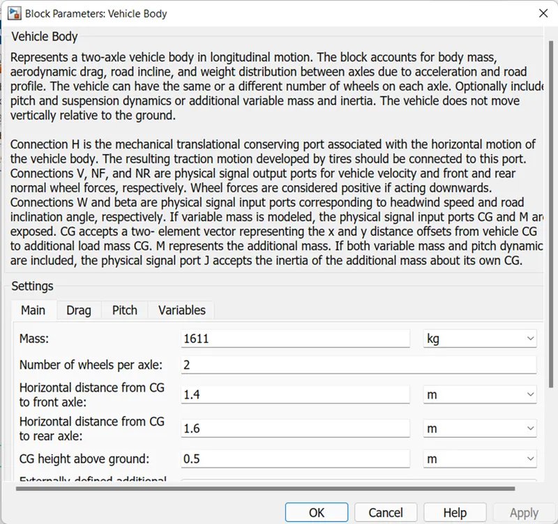
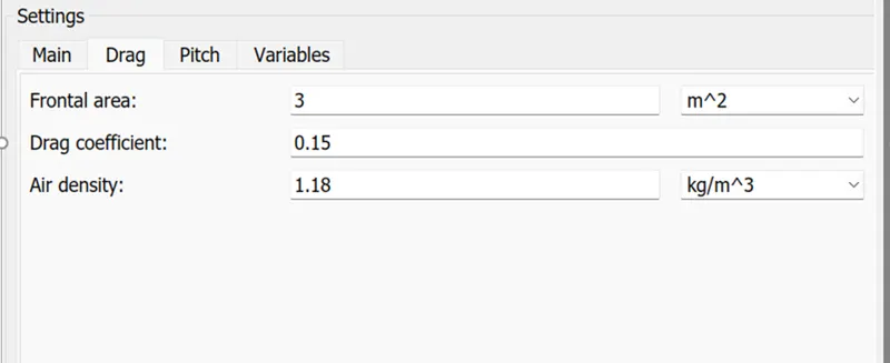
- These are the parameter seting for vehicle body.
2. Tire (magic formula)
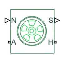
- The vehicle is assumed that front axle driven.
- In this model tire modeling we used tire(magic formula) which is shows in above picture.
- In this block port N is corrsponding with normal force of tire given by vehicle body block.
- Port A is axle of wheels and torque is given through this port.
- Port H is corrsponding to wheels hub through which thrust is devloped by tire is applied to vehicle body block.
- Port S is output port for slip of tire.
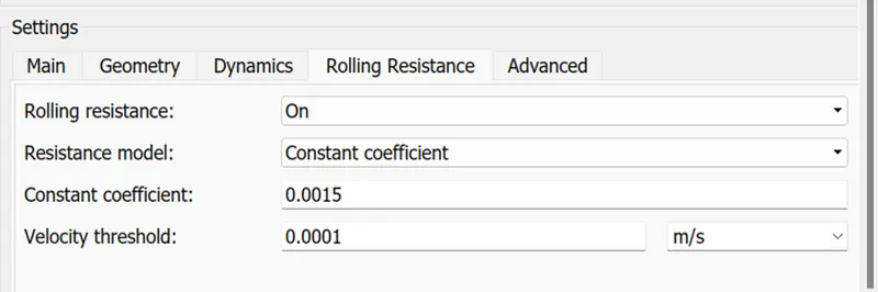
- Now we discuss about it’s parameter which given image in below.
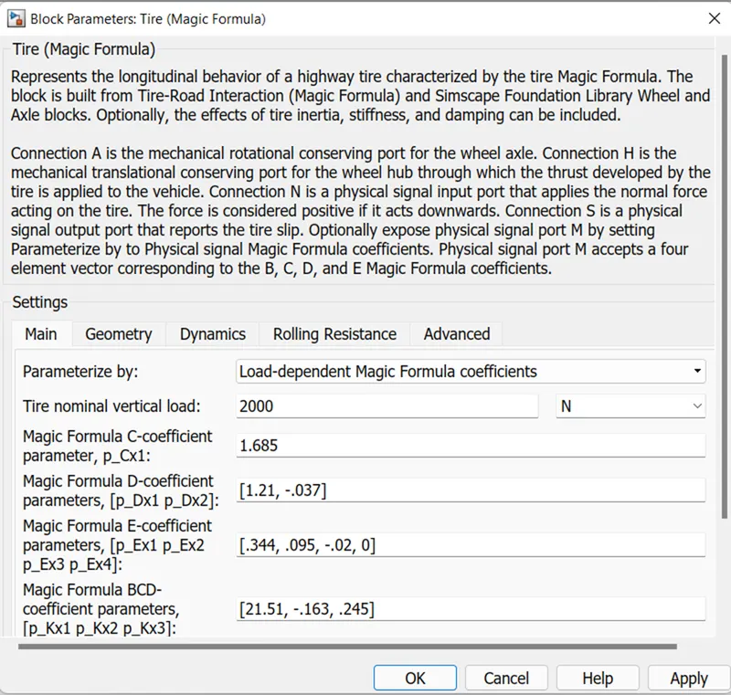
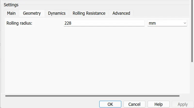
- For this here taking load depending magic formula coefficients for this tire and it’s parameter which is above shows in images.
3. Simple gear :-
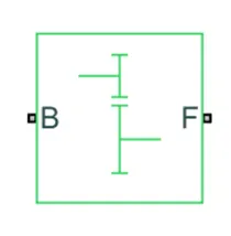
- This block is used to connect motor and front axle of vehicle with some gear ratio.
- Port B is input of simple gear block which is connect with motor shaft.
- Port F is output of simple gear block which is connect with front wheel axle of vehicle.
- Now we discuss about parameters in given image.
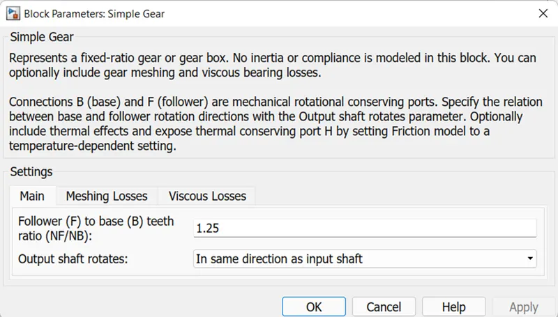
- In this output shaft rotates in same direction as input shaft and not taking mashing loss and viscous loss for this gear system.
3. Battery & SOC:-
- In this subsystem what we discuss of vehicle part which Is shows in below image.
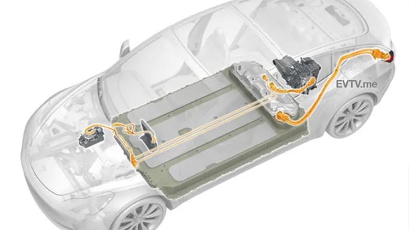
- In above image highlighted part is barrety cell which is discuss in this subsystem.
- In below image shows subsystem in model image.
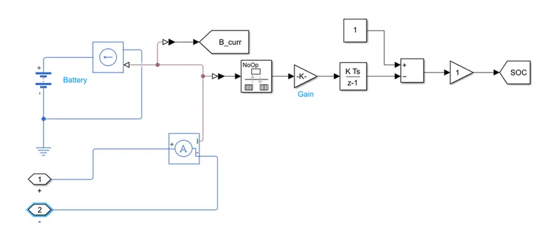
- In this subsystem we discuss about battery and state of charge for that we used blocks are battery, current controlled source, current sensor etc.
- Battery:-
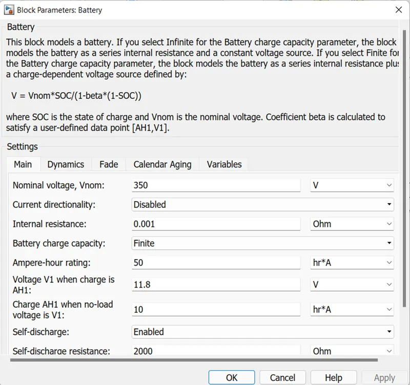
- This block is used for provided power to the motor but in this model we used internal battery too reduce simualtion time so here we used this battery for find SOC of battery.
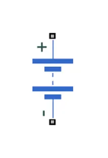
- This block paarameter is shows in below.
- In port + is provide positive signal of electric voltage.
- In port – is provide negative signal of electric referance.
4. Driver :-
- In this subsystem what we discuss of vehicle part which is shows in below image.
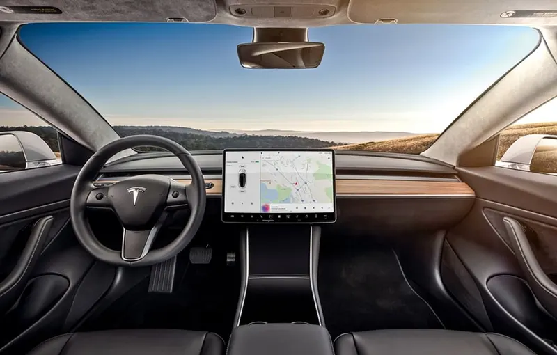
- In this image we can see that accelaration and brake pedal of this vehicle which discuss in this subsystem.
- In below image shows subsystem.
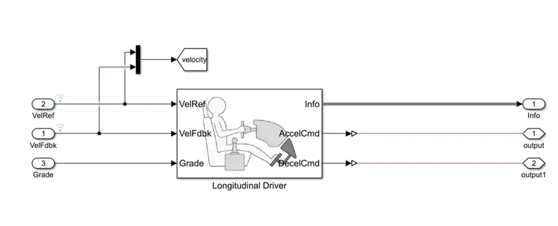
- Longitudinal driver:-
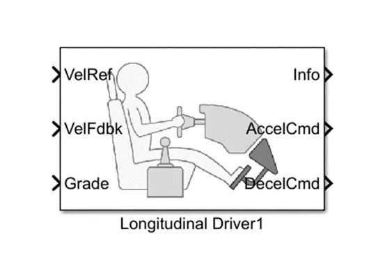
- This block is used to define the acceleration and brake from drive cycle and give value based on feedback value of velocity og vehicle.
- VelRef is input port which is received referance velocity.
- VelFdbk is input port which is received feedback velocityy of vehicle to smoooth operation of vehicle velocity.
- Grade is input port which is take road inclination angle.
- Info in this block we get information about acceleration, brake etc
- AccelCmd is output port which gives command of acceleratio
- DecelCmd is output port which gives command of deceleration or braking for vehicle.
- This block parameter is given in below image.
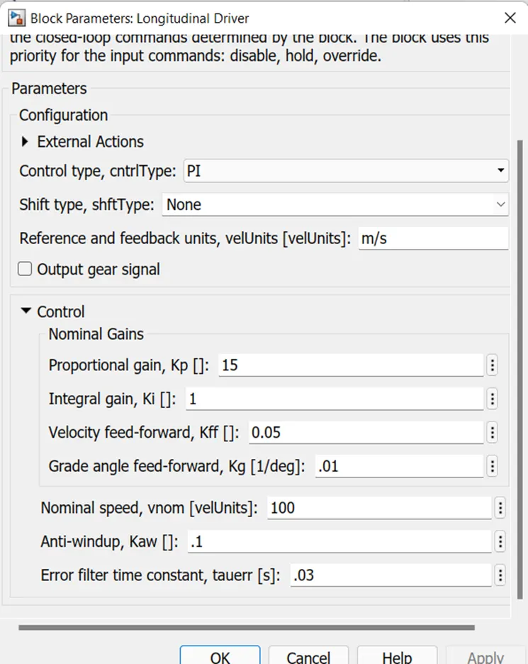
5. Drive cycle(referance velocity) input:-
- In this cycle input we can use many block like drive cycle, ramp, step, signal builder, repeating sequance or excel file which is has time and velocity data like look up table.
- In here this model we used drive cycle as input or source of input to longitudinal driver block in Velocity referance.
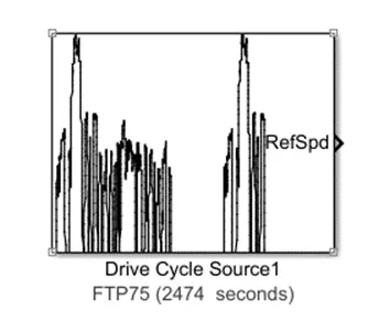
- In this block represent of speed Vs time data. It has irragular acceleration or deceleration value with respect to time.
6. Visualization :-
- In this subsystem we can visualize the all result which subsytem image is below shows.
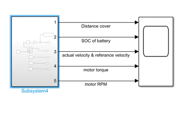
Now we discuss about simulation results.
- In this simulation results we see that accuracy of our design model and other parameter like how many km distance cover, what is SOC positon, moto current, motor torque etc.
- For the standard drive cycle which is name is FTP75 and see the result.
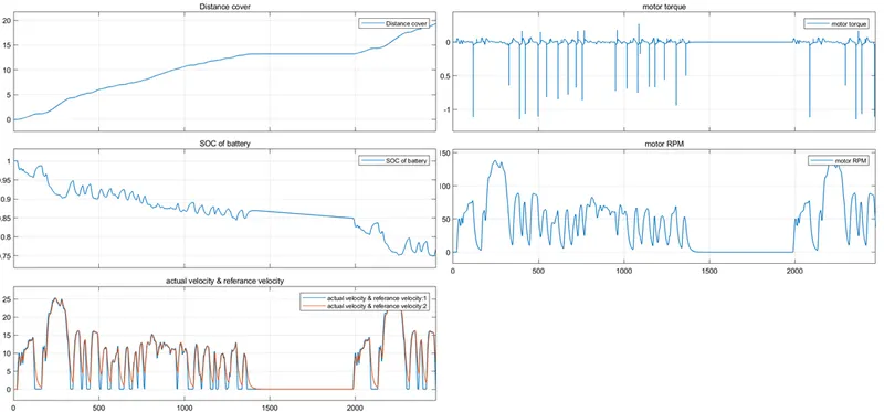
- In this graph (actual velocity & referance velocity) we can see that our actual velocity is following the referance velocity but there are some point when its not following because of motor inertial effect and other parameter which is may not fix as they have but its quiet following.
- And second is sudden change in velocity declaine or rising so its hard to follow but PWM mode may this not happpen.
- In graph(SOC of battery) we can see that 100% when start the cycle and end of cycle it’s around 78% and in between SOC is increase at some point because of regenerative braking happens when decelearation command is given in H-bridge.
- In graph(distance) we can see that cover distance slope is change because of change in acceleration and deceleration effect when high acceleration give then slope is high and vice-verse.
- In graph(motor torque) torque is suddenaly chagne based on requirement.
- In graph(motor RPM) here shows RPM at motor shaft which is more likely to drive cycle because it’s depend on the velocity of vehicle.
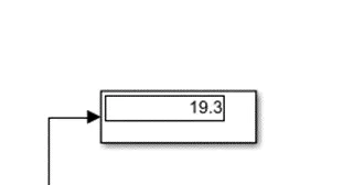
- Vehicle cover total distance 19.3km in througth the drive cycle.
CONSLUSION:-
- In this model we used FTP75 drive cycle for around 30 mins and total distance cover is 19.3 km and depth of charge is consume around 22%.
- From this simulation we learn about real time simulation for EV.
- How to configuration the parameter based on the other or as per requirement blocks.