Week-7 Challenge: DC Motor Control
Objective1: Speed control of a DC motor using BJT H-bridge.
Answer:
(a) In order to control the speed of DC motor, voltage fed to the armature of it needs to be controlled. A chopper can be used to control the voltage fed to armature of DC motor by controlling the switching frequency of the chopper switch. There different mode of operations in which a chopper can be classified. A typical chopper circuit is shown below
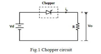
When firing pulse given to the semiconductor switch, the applied voltage appears across the load (neglecting the drop across the switch) and thus the average voltage across the load depends on the switching frequency of switch.
To understand the four-quadrant operation. Let us consider a H-bridge chopper, fed to the armature of a separately excited DC motor.
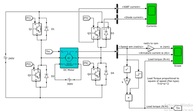
Here BJT are used for switching purpose, and anti-parallel diodes across them used for freewheeling condition. Firing pulses given to the BJT by using below firing scheme
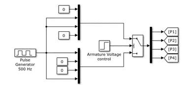
The control port threshold value is kept at 1, and armature voltage control is given at 0.5sec, so before 0.5 sec, Q1 and Q4 are switched ON and after 0.5 sec Q2 and Q3 switched ON
Mode1: Forward motoring mode
In this mode BJT Q1 and Q4 are switch ON, positive voltage appears across the armature, which derives the motor in forward direction
Mode2: Forward braking mode
Diode D1 and D4 conducts after Q2 operated to make the current direction negative
Mode3: Reverse motoring mode
Q2 and Q3 are switched on, so the current and voltage polarity get reverse, and the motor runs in negative direction
Mode4: reverse braking mode
Diode D2 and D3 conducts after Q4 operated to make the current direction positive.
In the above model a separately excited DC motor is used
The load torque is taken as fan type load
i.e.
(b)
The above model is simulated for 1 sec, the speed, armature current and torque plot is shown below
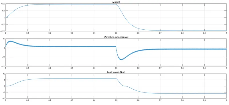
At t=0 sec, when Q1 and Q2 is turned on, as the motor pick up speed slowly so the back emf, as armature current is given as
As in the starting the back emf is low, so motors draws large amoount of current
Also at t= 0.5 sec, Q2 and Q3 is turend on, which forces the motor in reverse motorig mode, and as back emf get reversed so armature current at that instant can be given as
So at this instant there is a peak in armature current, which can be seen from the armature current plot.
(c)
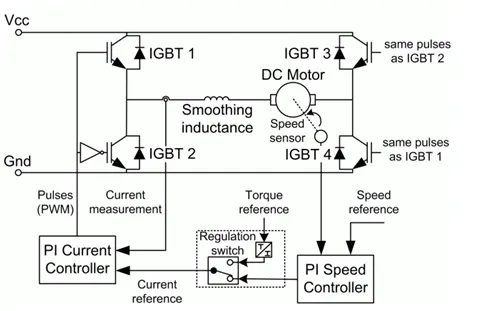
- The Four-Quadrant Chopper DC Drive (DC7) block
This drive uses IGBT as a switch
Compared to the H-bridge speed control drive, DC7 drive incorporates close loop speed control with four quadrant operation. Unlike H-bridge drive, DC7 gives firing pulses to the IGBT according to the requirement of speed and mode of operation, while in H-bridge drive the switching sequence is fixed.
In DC7 drive IGBT 1 and 2, IGBT 2 and 4 fired by same pulse
Using a PI controller to get the desired speed, the control loop manipulates the armature current to control the speed.
Also as IGBT can operate at high switching frequency, there will be lower ripples in armature current as compared to thyristor or BJT based drive.
Below shown is the
- The Four-Quadrant Chopper DC Drive (DC7)
Objective2: Develop a 2-quadrant chopper using Simulink
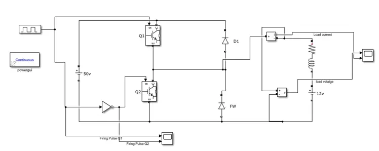
Simulation Model:
Working Principle:
Mode1: Q1 is operated
In this mode, switch Q1 is turned on, due to which positive voltage appear across the load, in this mode inductor stores energy
When Q1 is turned off, current flows through freewheeling diode
Mode2: Q2 operated
When Q2 is operated, direction of current changes, and inductor along with battery dissipates their energy in the resistance
When Q2 is turned OFF, current is fed back to the source through diode D1
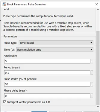
Pulse generator: The below specification of pulse generator is taken
Results:
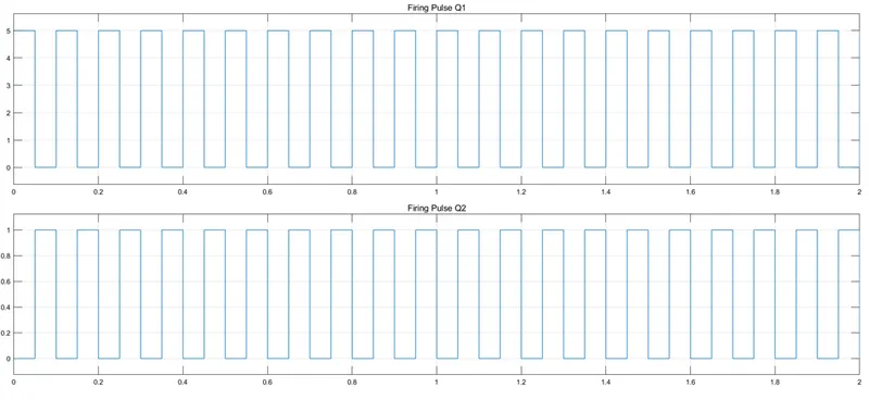
The firing pulse sequence to Q1 and Q2 is shown below, a pulse generator is used to for this purpose. From the below figure it can be seen that, Q1 and Q2 fired alternatively.
Load voltage and current plots:
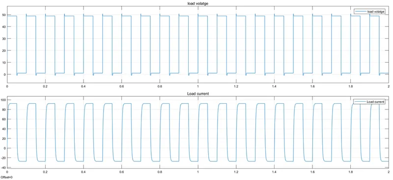
The load is taken RL type along with a battery of 12v to represent the back emf, and R and L to represent the motor parameter.
We can see that when Q1 is turned on source voltage appears across the load and load current increases. There is drop of about 1v which is due to the fact that Q1 has on state voltage of 1v
When Q1 is turned OFF and Q2 is turned ON, current freewheels through it in opposite direction.
Objective3:
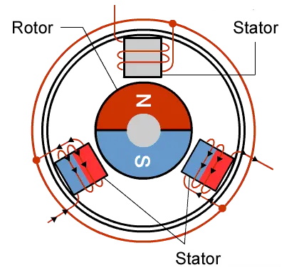
BLDC motor: Conventional brushed DC motor, which uses brushes and commutator to change the direction of current flowing in the rotor winding to get positive torque. There is always a problem of commutation in the conventional DC machines, where as brushless DC motors uses no brushes and commutator. IN BLDC motors the rotor is essentially made up of permanent magnet. In stator, there is arrangement of windings and they gets excitation in such a way that a positive torque is always produced, which can be seen from the below animation.
Advantages of BLDC:
More powerful than conventional DC motors.
Have wide range of speed control
As no brushes are used, so less noisy.
High durability, as less maintenance is required.