Project-1: Powertrain for aircraft in runways
Part A:
- Weight of various types of aircrafts are mentioned below
|
Aircraft Name |
|
|
Max Gross Takeoff Weight |
|
|
1,411,000 lbs |
||||
|
1,268,000 lbs |
||||
|
987,000 lbs |
||||
|
820,000 lbs |
||||
|
776,000 lbs |
||||
|
560,000 lbs |
||||
|
187,000 lbs |
||||
|
150,000 lbs |
||||
|
106,000 lbs |
||||
|
100,000 lbs |
||||
|
80,500 lbs |
||||
|
62,000 lbs |
||||
|
21,500 lbs |
||||
|
17,200 lbs |
||||
|
12,000 lbs |
||||
|
4,400 lbs |
||||
|
3,660 lbs |
||||
|
3,600 lbs |
||||
|
3,600 lbs |
||||
|
2,425 lbs |
Reference: https://pilotteacher.com/how-much-do-airplanes-weigh-with-20-examples/
- Difference between ground and airspeed.
Ground speed is the speed of aircraft with respect to ground, which is dependent on the direction and speed of the wind, and on the other hand Airspeed is the actual speed of the aircraft, or we can say the speed of the aircraft by its own power.
This can be understood in a simple way, suppose on a still day when there is no wind which can either help of opposing the aircraft speed, the Ground speed will be equal to the Airspeed of the aircraft. If there is wind blowing which supports the aircraft speed, then aircraft speed with respect to ground is more than the aircraft airspeed, and when the wind opposes the aircraft speed then the Ground speed is less than the Airspeed.
An animation for tail and headwind is shown below.
Reference:
https://basicmahiti.com/generalknowledge/what-is-the-difference-between-air-speed-and-ground-speed/
- Most of the aircraft are unable to move in the reverse direction as the aircraft propeller is not designed to produce thrust in the backward direction, and also the if reverse thrust is used to move the aircraft back, there will be an increase in the power hazard area, which can cause damage to equipment or people working nearby.
A typical jet engine used in aircraft can reach up to 600 km/h immediately after the engine is turned on which can cause severe air flow, which may lead to damage of equipment, nearby airport building area and persons working there. So pushback trucks are used to carry the aircraft up to run way, and after the aircraft reached to the run way or taxing position jet engines starts.
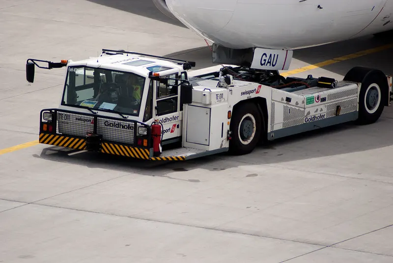
4. Generally push back trucks are used to move the aircraft to taxiing position. This can be done in two ways.
Towing by tugging: It is the conventional or old, method to move the aircraft, in which at the nose landing gear by using locking pins towing operation is carried out.
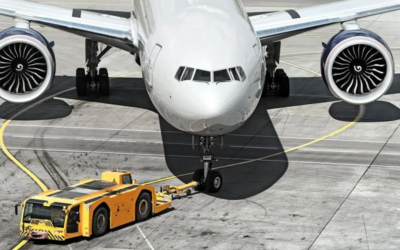
Towbar less tug: This type tugging is now more common, in which the nose landing gear is raised to be fitted in the truck. Low profile push back trucks are used, so that they can easily be fitted under the nose of aircraft.
Reference:
https://skybrary.aero/articles/aircraft-towing
- Take off power: It the power required by the aircraft to reach to minimum safe velocity, so that after take off it can achieve desired height.
The aircraft is accelerated till it reaches initial safe speed, after the with the help of aileron necessary thrust force is produced to lift the aircraft from the ground. For small aircraft safe flying speed VR is determined as 1.1*Vstall and thrust force at the time of take off can be given as
T= M*a+D+F
Where: a is acceleration, D is drag force, F is the traction force
VSTALL, is the lowest speed that the aircraft can be flown before the airflow starts to separate from wings
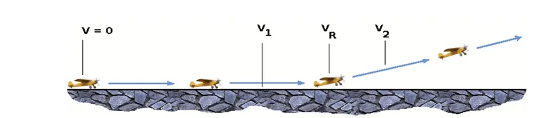
For transport aircraft: V2 must be no less than 1.2 * Vstall.
VR must be set so that aircraft achieves V2 before reaching a height of 35ft above the runway surface.
Aircraft must climb at a minimum gradient to avoid obstacles at the end of the runway. With engine failure on multi-engined aircraft, this speed should still be achievable.
Rolling Resistance: It is the friction offered by the run way to the tires of the aircraft, which is proportional to the normal force exerted by aircraft and can be given as:
Where W is the weight of the aircraft and L is the lifting force exerted by the aircraft, and is the coefficient of friction, which is typically 0.02 for standard tarmac runway.
Tyre design and pressure: An aircraft tyre is deign to meet cool running, heat-resistance, less , maintenance required. Generally two types of deigns are used
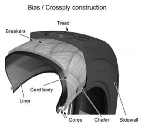
1: Bias-ply tire: This type consists of following specifications:
Tread: The tread is constructed of rubber that has been blended with additional compounds to achieve the desired toughness, durability, and wear resistance. The tread pattern is tailored to the needs of the aircraft, with the ribbed tread design being popular because of its excellent traction in a variety of runway conditions.
Sidewall: The sidewall is a rubber covering that protects the outer casing ply from damage. It stretches all the way from the tread edge to the bead area.
Buff line cushion: To improve adhesion between the tread reinforcing ply and the breakers or casing plies, the buff line cushion is comprised of rubber compound. It has enough thickness to allow the old tread to be removed when the tyre is retreaded.
Breakers: Breakers are rubber-coated fabric plies that are inserted beneath the buff line cushion to protect the casing plies as well as strengthen and stabilise the tread region. They are regarded as an essential component of the casing's construction.
Chafers: A protective layer of rubber or favric is placed between the casing plies and the wheel.
Casing piles: The tire's strength is provided by alternating layers of rubber-coated fabric.
Liner: The liner works as a built-in tube in tubeless tyres, preventing gas from diffusing into the casing plies. To reduce tube chafing against the inside lining, tube-type tyres have a thinner liner.
Note: A radial trailer tire is constructed with steel belts of the tire running at a 90 degree angle of the tread center line.
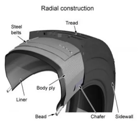
Radial-ply tire: They give improved landings and lower rolling resistance because to their stiff belt. They feature fewer parts in their design and are lighter than bias ply tyres of comparable size. The following are components that differ from bias-ply construction:
Overlay: To aid in high-speed functioning, a layer of reinforcing rubber coated fabric is added on top of the belts.
Belt Plies: A composite structure that stiffens the tread area and allows for more landings. The tread area of the tyre is strengthened by the belt plies.
Casing Plies: The casing plies are rubber-coated fabric layers, similar to bias-ply tyres. Radial plies, on the other hand, travel radially from bead to bead, unlike bias plies, which run at right angles to one another.
Chippers: The chippers are rubber-coated fabric layers put at diagonal angles to improve the tire's bead region durability.
Note: A bias ply trailer tire is constructed with nylon belts of the tire running at a 30-45 degree angle of the tread center line.
Tyre pressure: An aviation tyre, is made to bear exceptionally severe loads for brief periods of time. Aircraft tyres are typically operated at high pressures, up to 200 pounds per square inch (psi) for airliners, and even higher for business jets. Nitrogen is commonly used to inflate aircraft tyres to reduce expansion and contraction caused by dramatic fluctuations in ambient temperature and pressure encountered during flight.
Brake force: On every wheel of aircraft there is a brake assembly, which stops the aircraft with in the safe distance. Along with mechanical brakes on tyres, aerodynamic brakes are used, which involve opening of flap to increase the drag force to reduce the stopping distance.
Now hydraulic actuated brakes are being replaced by electrically actuated brakes, in which an electreic signal is sent to brake unit in the wheel, which then press carbon brake disc against the wheel to slow it down.
Refrences:
http://www.aerodynamics4students.com/aircraft-performance/take-off-and-landing.php
https://recstuff.com/pro-tips/radial-vs-bias-ply-trailer-tires-whats-the-difference/
https://thepointsguy.com/guide/how-do-aircraft-brakes-work/
Part2
- To calculate the force and power required to push / pull an aircraft by a towing vehicle.
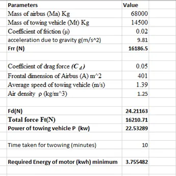
The total tractive force required by the towing vehicle should overcome, rolling resistance force, aerodynamic drag force.
Rolling resistance force:
M is the total mass of aircraft and the vehicle itself
Mass of Airbus A320-100 Ma =68000kg
Towing vehicle mass Mt=14500 kg
g is acceleration due to gravity 9.81m/s^2
and for tarmac coefficient of friction µ is about 0.02
g
So, Frr = 0.02(68000+14500)*9.81
= 16186.5 N
Aerodynamic drag force: Fd
Where ρ is air density = 1.25 kg/m^3
Cd is drag coefficient = 0.05 for Airbus A320-100
A is frontal area
Length (wing span) = 34.09 m
Height (top of tail) = 11.76 m
A = 34.09*11.76
= 401 m^2
Average speed of towing vehicle is 5 kmph or 1.39 m/s
So Fd = 0.5*1.25*401*0.05*1.39^2
= 24.21 N
Therefore total force required is = 161886.5+24.21
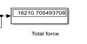
Ft = 16210 N
Hence power of towing vehicle for an average speed of 5 kmph or 1.39 m/s
P= Ft*V
=16210*1.39
=22.5 kW
- Develop the model for the calculated force and power using Simulink.
Simulink model to calculate towing vehicle force and power is shown below.
Constant block is used to call variables from the work space
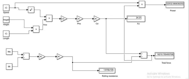
Constant blocks are used to call variables from the work space
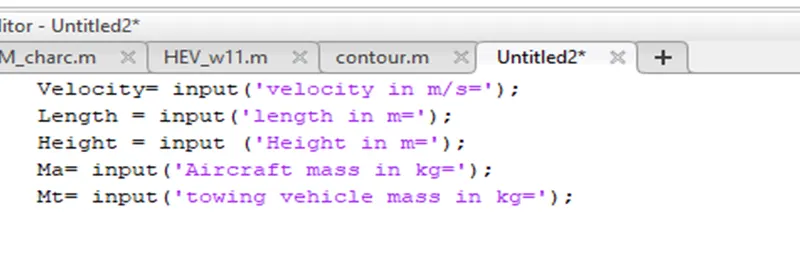
Following specifications have been taken
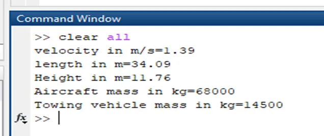
Gain blocks are used for, air Cd is drag coefficient = 0.05, coefficient of friction = 0.02 and drag coefficient = 0.05 is taken.
Summation block is used for adding rolling resistance and drag force.
The required vehicle force in N is displayed:
The required vehicle power in Watts is displayed:
- To fulfil the requirement of power, energy or force by the tug vehicle. Considering the motor used in tug vehicle as permanent excited DC motor, whose power rating 25kW.
Let the time taken by the towing vehicle to pull the aircraft to the runway is 10 minutes at an average speed of 5 km/h so the energy required is = 25*10/60= 4.17 kWh
Let the battery used to power the motor has nominal battery voltage of 450V and the rated voltage required by the motor of towing vehicle is 400V.
If a power converter is being used to step down the battery voltage. So to get the rated voltage i.e. 400V in order to have rated speed of towing vehicle duty ratio can be calculated as:
Vo= DVin
Here Vin is 450 and Vo is 400V
D= V0/Vin= 400/4500
D= 0.89
So the range of duty cycle to control the aircraft speed from zero to rated speed is 0 to 0.89.
|
Parameters |
Assumptions |
|
Mass of airbus (Ma) |
68000 kg |
|
Mass of towing vehicle (Mt) |
14500 kg |
|
Coefficient of friction (µ) |
0.02 |
|
Coefficient of drag force (Cd) |
0.05 |
|
Air density (ρ) |
1.25 kg/m^3 |
|
Frontal dimension of Airbus |
34.09*11.06 m |
|
Average speed of towing vehicle |
5 kmph |
|
Nominal battery voltage |
400 V |
|
Time taken for towing |
10 minutes |
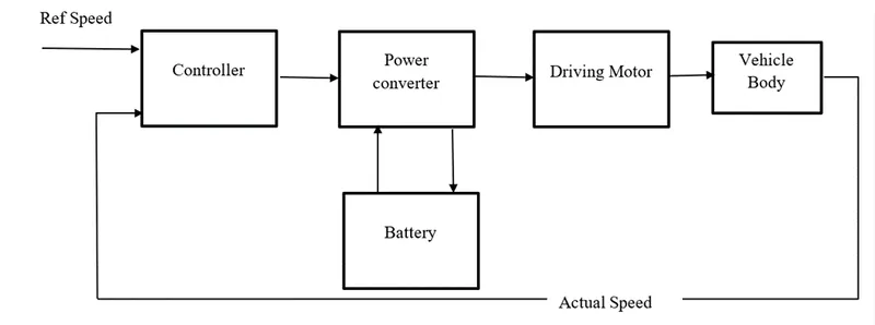
Block diagram:
Refreneces:
https://modernairliners.com/airbus-a340-specs/
https://eagletugs.com/aircraft-tugs/eagle-xm-series-aircraft-tugs-xm-30
B