Week -2
Objective1: To develop Simulink model of Doorbell using a solenoid with the switch is closed for 2 seconds and then released.
Theory: Conventional doorbell uses a special type of electromagnet called Solenoid. In which there is a coiled wire surrounds a magnetic material called plunger. When current passes through the coil, flux through the coil changes which forces plunger to move either inside or outside, which depends on the initial position of plunger to oppose the change in flux. Plunger due to its oscillations in the position hits the bell and produces sound.
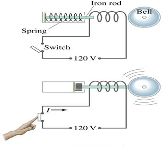
Simulink model: Simulink model with its model description is shown below.
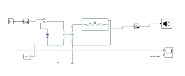
Model description:
Pulse generator: To provide input pulses to the switch.
Simulink to PS converter: To convert Simulink signal to physical signal.
Switch: Single pole single through switch, to connect the battery to solenoid.
Battery: To energize solenoid, 12 V used here.
Solenoid: To produce magnetic field which make the plunger move.
Electrical and mechanical reference.
PS to Simulink converter: To convert physical signal to Simulink signal.
Scope: To view the position of plunger and pulse given to switch.
Results and discussion:
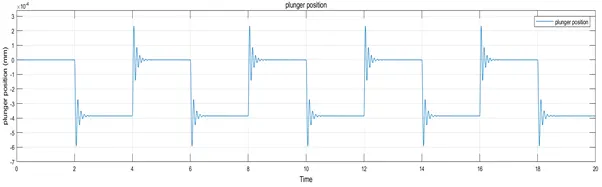
- To close the switch for 2 seconds, repeating pulse of time period of 4 seconds and duty ratio of 0.5, of magnitude 1 is used.
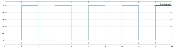
- Initially, plunger was completely out of the air gap and this position is assumed to be zero position.
- When the switch closed at t = 2 sec, plunger moves inside the coil to oppose change in flux and strikes with the bell to produce sound.
- After t = 4 sec, when the switch opened again which forces plunger to come back to its position again.
- The plunger did not settled to its equilibrium position suddenly as it has some moment of inertia, thus oscillations can be seen in the figure below when the plunger moves to another position.
-
Note: Plunger position is in mm.
Objective2: To sense the temperature of a room using thermistor and turn ON the fan when temperature is above 25oC and turn OFF the fan when the temperature is below 25oC.
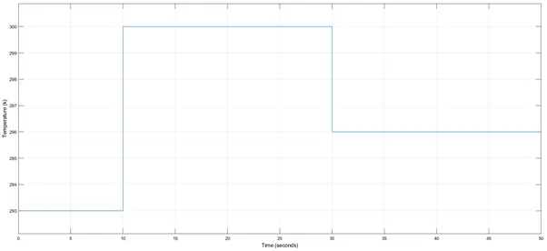
Given conditions for temperature source: 20oC or 293 K from 0 to 10 seconds, 27oC or 300 K from 10 to 30 seconds, 23oC or 296 K from 30 to 50 seconds
Theory:
A Thermistor is a solid state device used to sense temperature by calculating output voltage or current from it. There are two types of thermistors:
(1) Positive temperature coefficient (PTC): Resistance increases with increase in temperature.
(2) Negative temperature coefficient (NTC): Resistance decreases with increase in temperature.
Here the type of thermistor used for simulation is NTC type.
-
Simulink model:
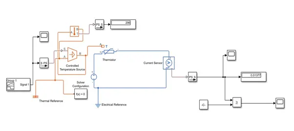
Model description:
Signal builder: Used to provide input temperature in kelvin (K) to the controlled Temperature source
Controlled temperature source: Represent ideal energy source to maintain a controlled temperature. In which port B will be at higher temperature with resp. to port A for positive temperature.
Thermistor: An NTC type thermistor was used as a temperature sensing element, whose output current measured by a ideal current sensor to provide logic input to fan switch.
Voltage source: 15 volts battery used in the thermistor circuit.
-
Results and Discussion:
First the temperature of controlled temperature source was set to 25oC or 298 K to calculate threshold value of current using current sensor to find the condition to turn ON the fan which comes out to be 0.01491A. So when the temperature increases beyond 25oC or 298 K the control logic should go high - Figure below shows Temperature (K) vs Time plot as per the given conditions
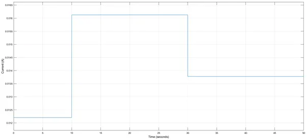
- The variation in output current from the thermistor for various temperatures is shown below. From the plot it is evident that, with the increase in temperature of the thermistor, output current through it increases as the resistance of NTC type thermistor decreases with increase in temperature and vice-versa.
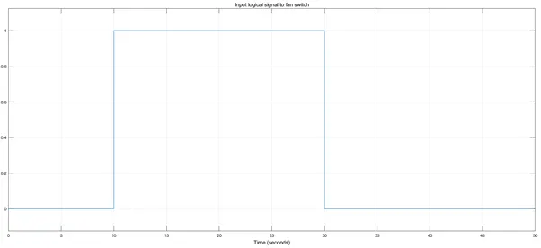
- Figure below shows the control logic input to turn the fan ON and OFF as per the conditions. From the plot it can be seen that when the temperature is greater than 25oC or 298 K the control logic goes high from 10 to 30 seconds, which will turn the fan ON and when the is less than 298 K the control logic goes low to turn the fan OFF.