Week - 4
Objective1: To implement control logic of washing machine using state flow for following conditions:
- Activate the system when power supply is available
- If water is not available, stop the process and indicate through a LED
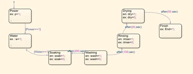
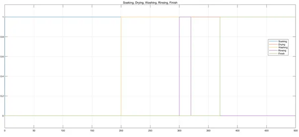
- Soaking time of 200s followed by washing time of 100s, after that rising for next 20s and drying for 50s
Simulink Model:
The Simulink model, based on above conditions using state flow technique is shown below
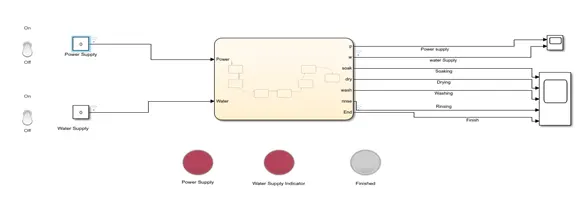
Model description:
Dashboard switch: To ONN and OFF power and water supply.
Constant: To provide control logic input of power and water supply to state flow chart
Lamp: To indicate the state of power, water supply and to show if the process is finished or not.
Scope: To view the states of different required processes.
State flow chart is shown below:
Results and Discussion:
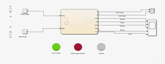
1. When the power and water supply both are off, which is shown by red indicators
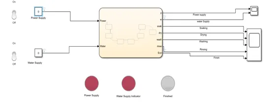
As there is a condition when Power==1, only then power state will exit and other state will get executed, as power is switched off execution of states stops at power state.
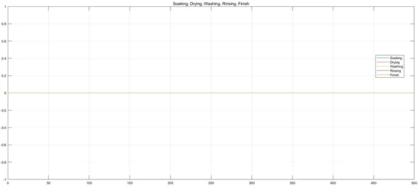
2.When power supply is switched ON but water supply is switched OFF
Condition of water supply (water==1) violates so execution of states stops as water state.
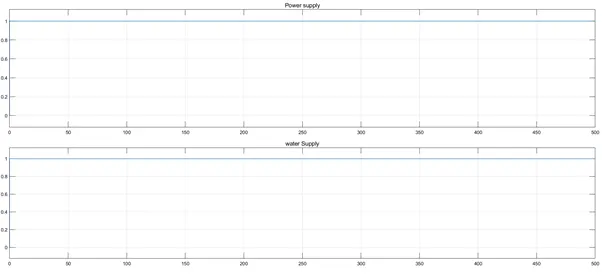
3. When both power supply and water supply are switched ON
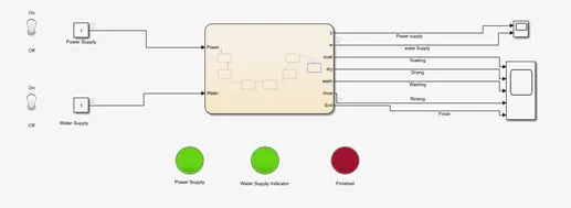
As both condition of power and water supply meets, execution of all states takes place and when the process finishes, will be shown by red indicator as shown above.
Soaking, washing, rinsing and drying state is shown below as per the given conditions
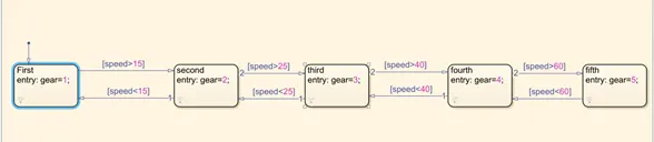
Objective2: To make a Simulink chart for ‘Gear shift logic’ as per following conditions:
Speed range (kmph) gear
0 to 15 1
16 to 25 2
26 to 40 3
41 to 60 4
0Above 60 5
Simulink model:
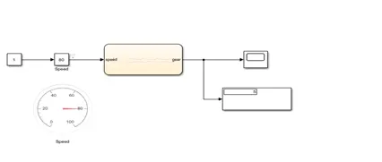
Model description:
Slider gain: To give speed input at the time of simulation
Speed gauge: To see given speed
Scope, display to show gear state
Sate flow chart pertaining to required condition is shown below
Results and discussion:
State of gear for various speed is shown below
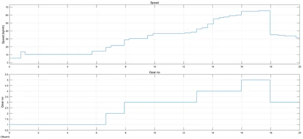
Initially when the speed is less than 15 (kmph) the gear no is 1 and as the speed increases the gear no too increase according to given speed conditions which can be seen from the above speed and gear no plot