Week 7 Challenge - Assembly Workbench
Assembly Workbench
In this challenge I create CADPart and assemble all the CADpart to the single product. After creating the CADpart I drafting the views and dimensioning it. Here I create two product design. The two products are,
1)Quick Returning Mechanism
2)CV Joint
CADProduct-1(Quick Returning Mechanism)
In this assembly totally 5 CADparts are created from the 2d drawing which given in the question.
The five parts are
- Bull gear
- Rocker arm
- Arm driver
- Sliding body
- Crank
1.Bull Gear
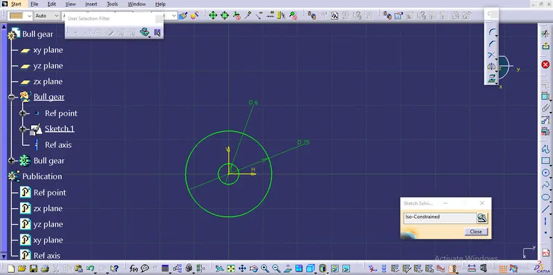
Sketch
This is screenshot of the sketch solving tool box. Here the circles are created for make solids.
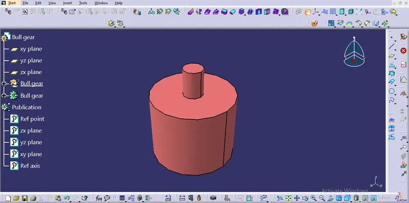
Part
Here I use multipad for make it as a part
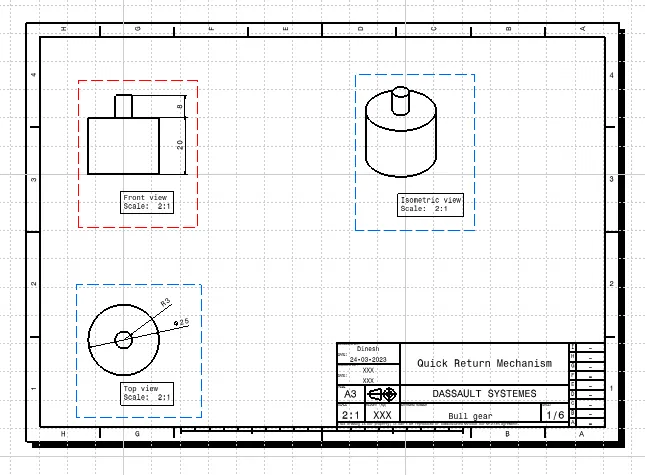
Drawing
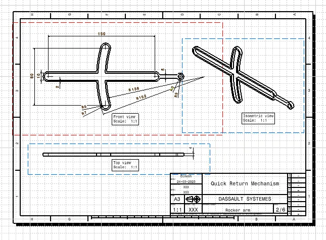
2.Rocker arm
Sketch
I create three part of sketch to make it is easy
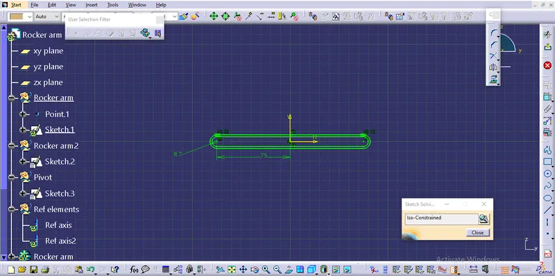
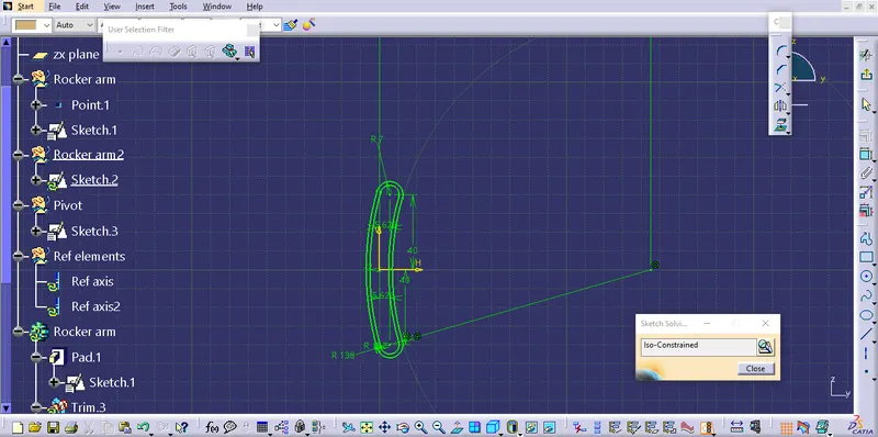
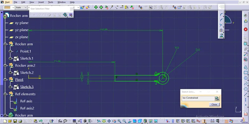
Part
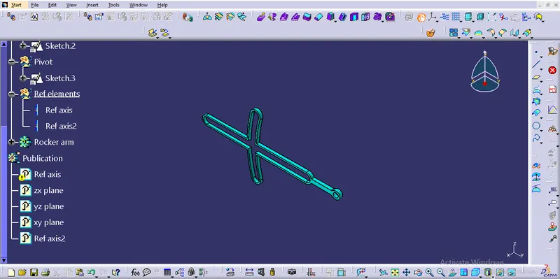
After sketching I make it as a individual solids.
And using tool called UNION TRIM(Boolean operation) trim the unwanted faces from the solids. Finally I got the part like this.
Drawing
3.Arm driver
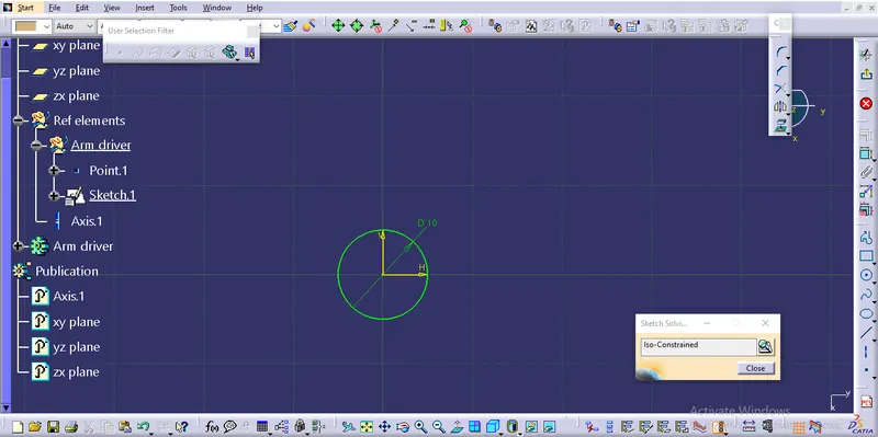
Sketch
I simply create a circle for it.
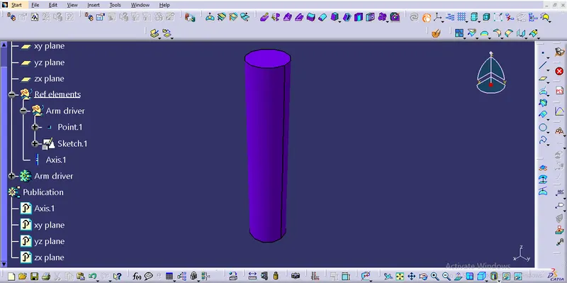
Part
And pad it for getting the required length.
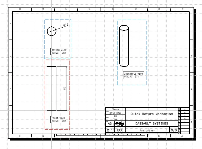
Drawing
4.Sliding body
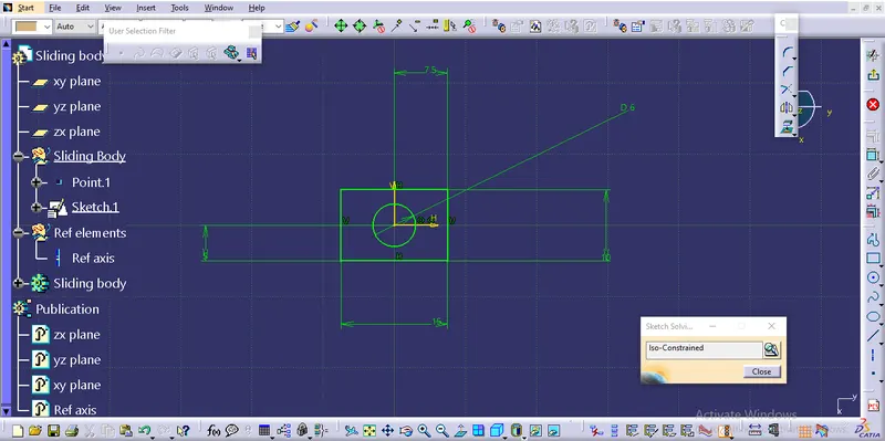
Sketch
Same as arm driver I just create the circle and rectangle.
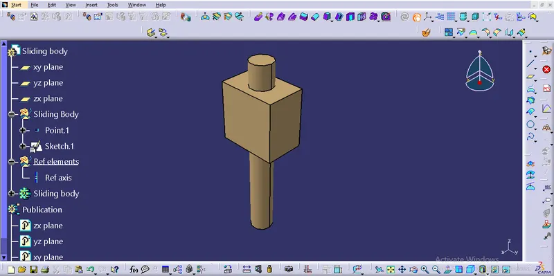
Part
After sketching I'm used PAD tool and given the inputs in two opposite directions.
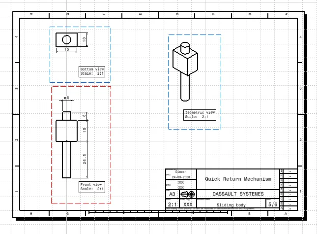
Drawing
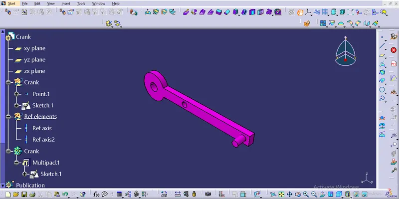
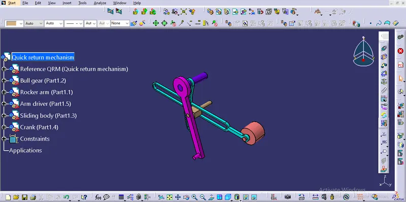
5.Crank
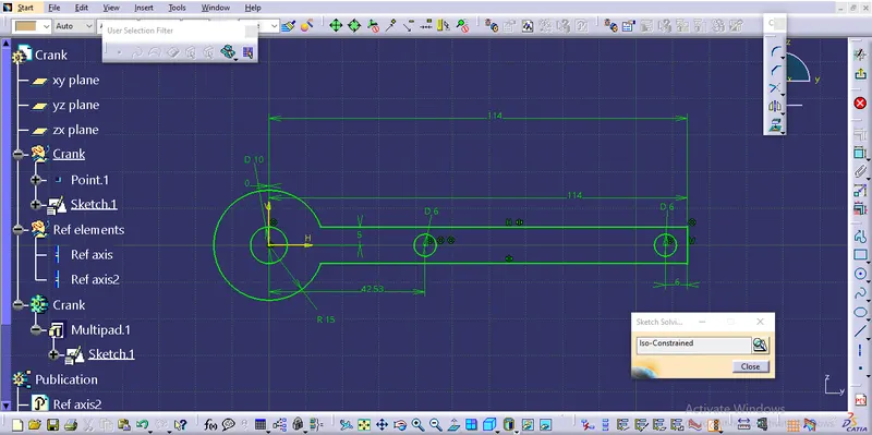
Sketch
This is little bit tasky sketch compared to other part sketches.
Part
Same PAD tool is ued to get the exact part which given in the question.
Drawing
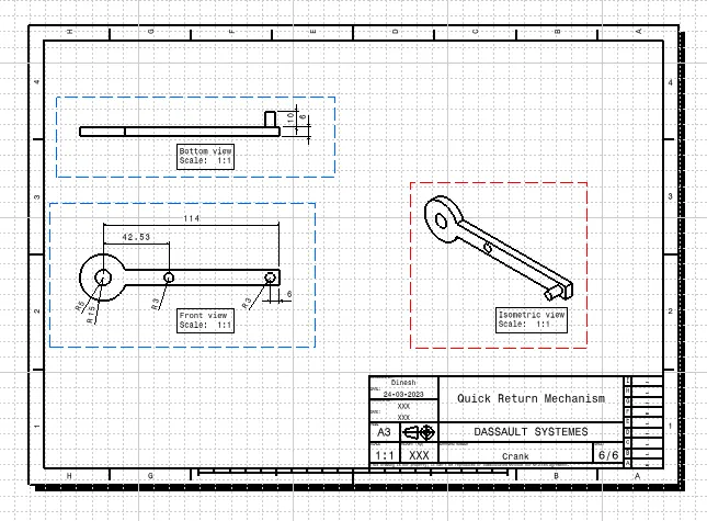
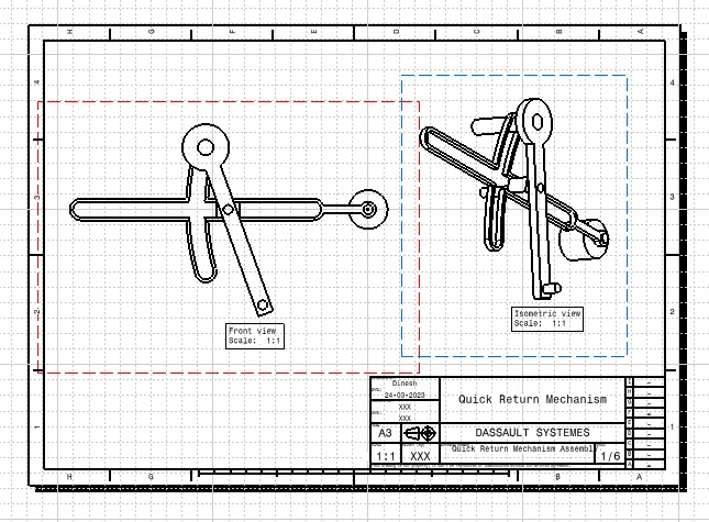
Assembly of quick returning mechanism
I assemble all the CADparts respect to the constraints and drawing which was given to the question
Drawing
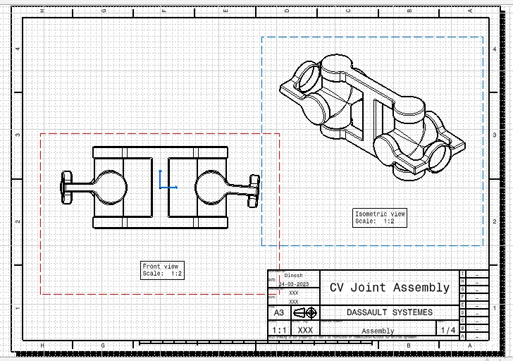
CADProduct-2(CV Joint)
In this assembly totally three parts are created and two parts are copy pasted. The three parts are created from the 2d drawing which are given in the question.
The three parts are
- Body1
- Body2
- Body3
1.Body1
Sketch
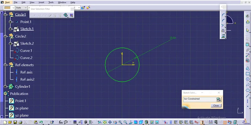
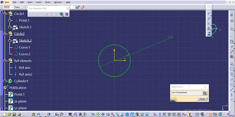
I created two circles in different planes to get the required part.
Part
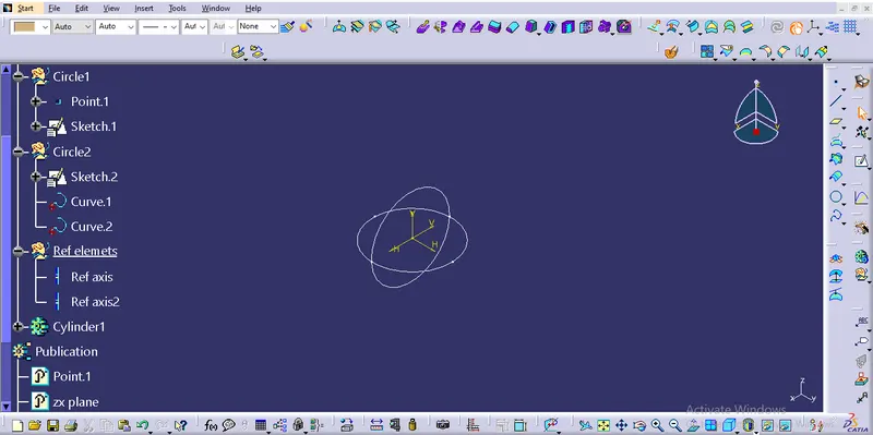
The two different plane circles are extruded with a length of 100mm.
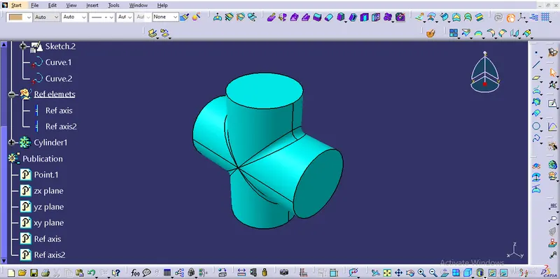
These two solids are compined by the tool called ADD(Boolean operation)
And finally edges are covered with fillets.
Drawing
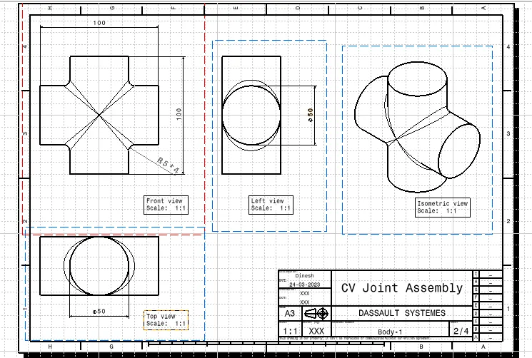
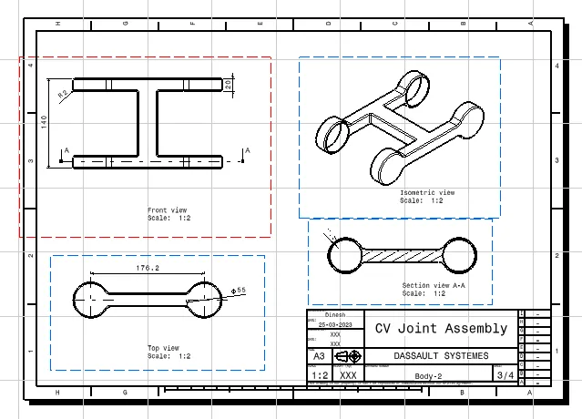
2.Body2
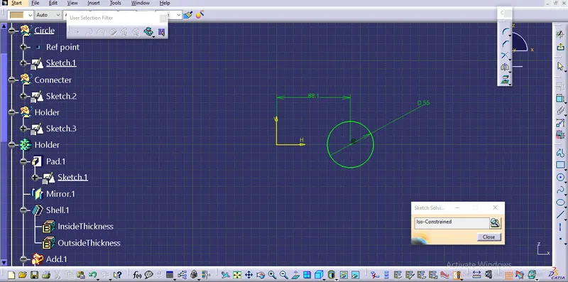
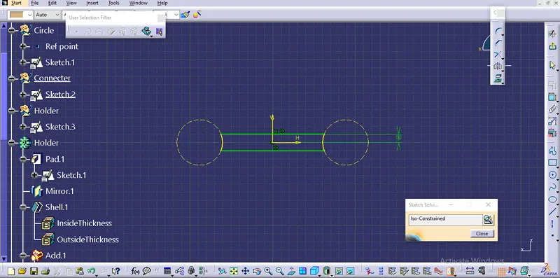
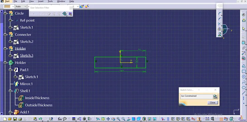
Sketch
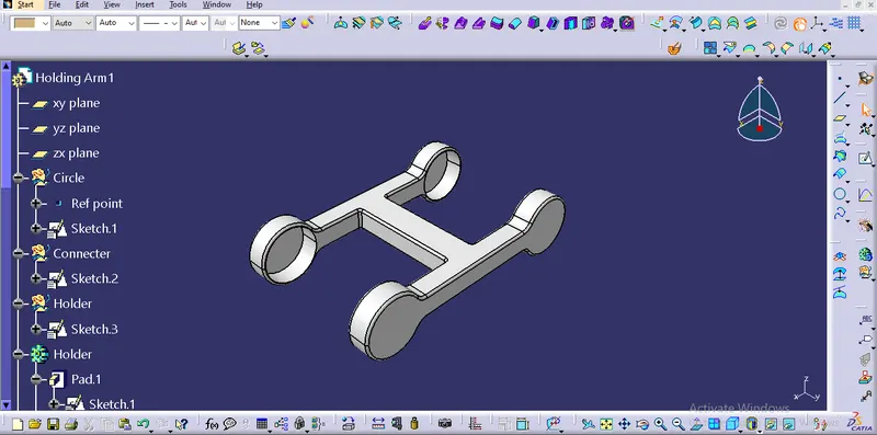
Sketches are created for first half and after extruding the sketches solids are mirrored to other half.
Part
Here I used PAD and MIRROR tool
ADD(Boolean operation) tool is used to combine all the solids which are present in the screen.
Drawing
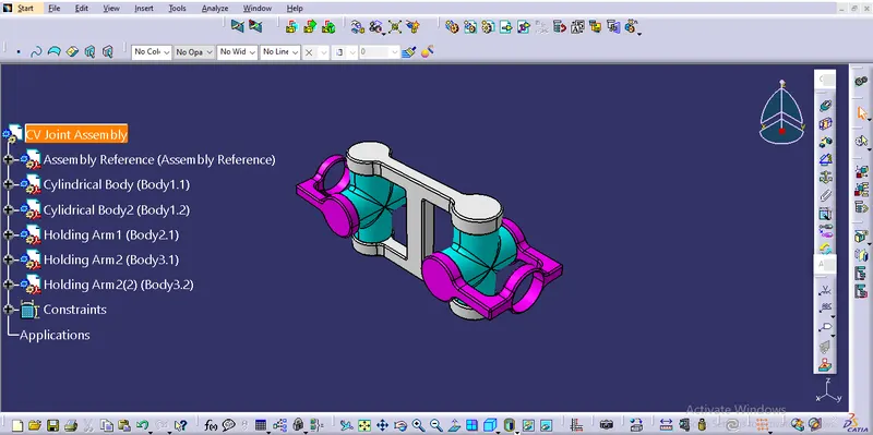
3.Body3
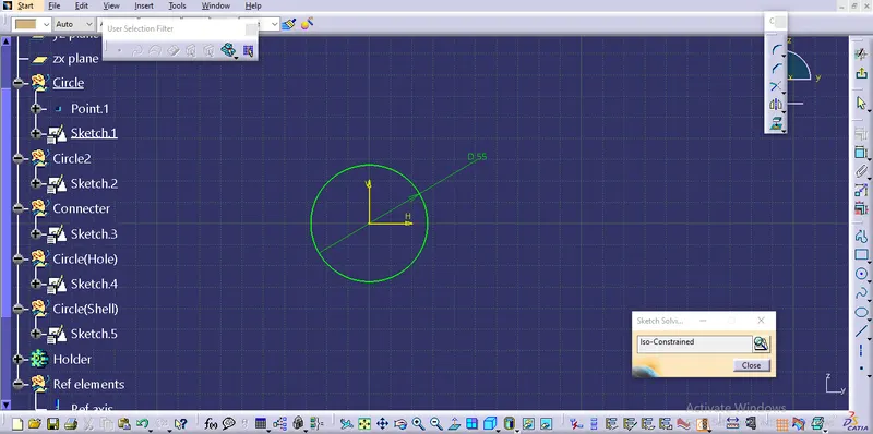
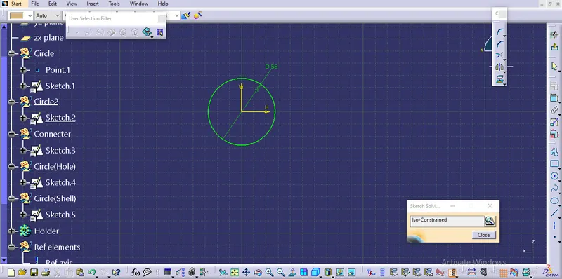
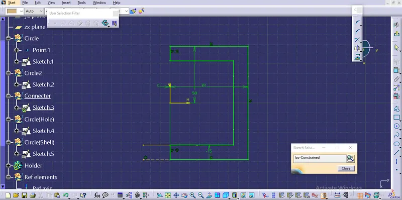
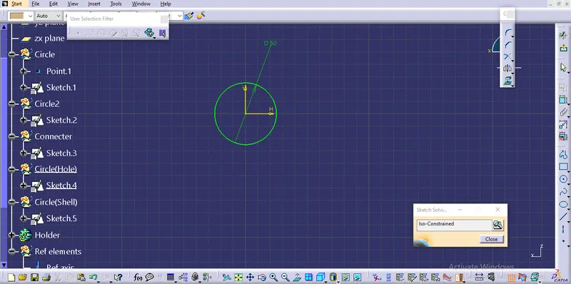
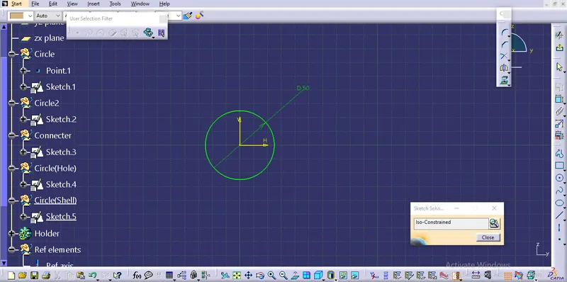
Sketch
The same stratagy was used here to create all the sketches.
Part
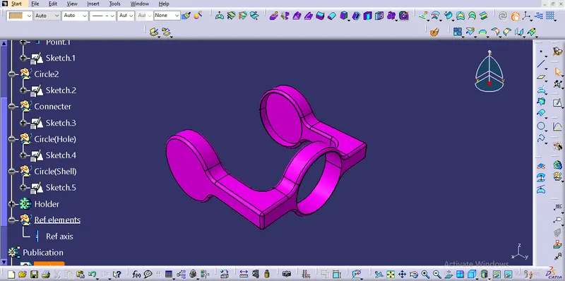
Part was created by the tools called
PAD, ADD, UNION TRIM and REMOVE(Boolean operations)
Drawing
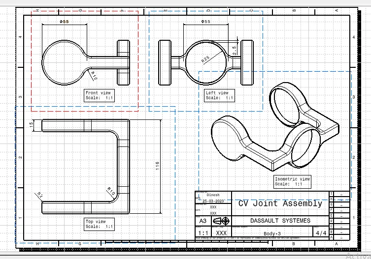
Assembly of CV joint
The assembly was just created by the constraints tools. Here every parts axis and points are published for future references
Drawing