Week 9 - Challenge 2 - Switch Bezel Design
Switch Bezel Design
Create the Switch Bezel Plastic component through the given Class-A surface. To begin with, the tooling axis for the given Class-A Surface should be created meeting the requirements of the draft angle and at the end perform the Draft analysis on the model.
Design Requirements
- Tooling Axis
- Class A surface
- Class B Surface
- Class C Surface
- Solid Plastic
Publication
The tooling axis class A, class B and class C surfaces are published using the publication option. This publication option helps designer to get more efficient results.
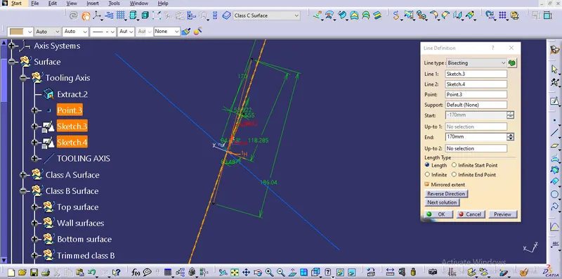
Tooling Axis
First the dummy tooling axis was created in the sketch and using bisecting tool a center line created from two surface after projecting the surface as intersecting lines. Finally the tooling axis was plotted by two different bisecting lines.
Class A Surface
The class A surface was already given in the question for design other B and C class surfaces with respect tooling direction. The tooling direction plotted from the class A faces which are inclined to the imaginary tooling axis.
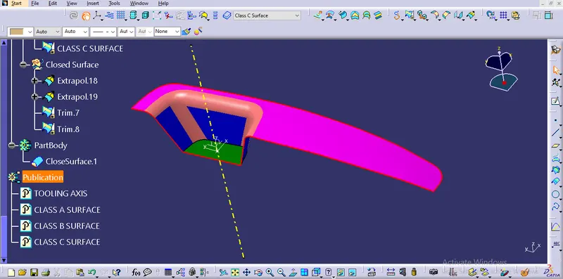
Class B Surface
extracting the class A faces and untrim the faces helps to get approximately required surface. After that extrapol all the surfaces and trim it to desired shape helped me to got this class B surface. It is offsetted below the class A surface of 2.5mm.
Tools used
- Exract
- Untrim
- extrapol
- trim
- Edge fillet
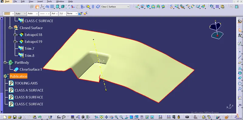
Class C Surface
Class C surface creation took lot of effect because of the discontinouse tangency in the boundary. For that I'm used multible exract tool in three different areas and reduce the vertexes in the boundary using smooth curve. The boundaries are extuded by sweep tool for three different tangent areas. Every edge of the sweep extrapol is executed for 10mm and trimmed for getting the one complete surface.
Tools used
- Multible exract
- Smooth curve
- Sweep
- Extrapol
- Trm
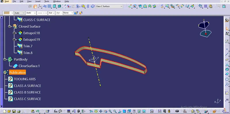
After that class A, class B and class C surfaces are trimmed together for getting the closed surface.
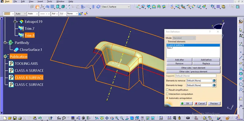
Solid Plastic
Using close surface option the closed surface was made as solid plastic.
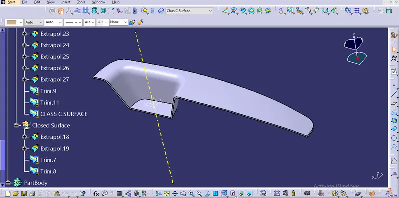
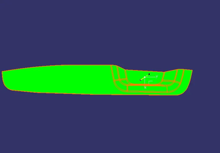
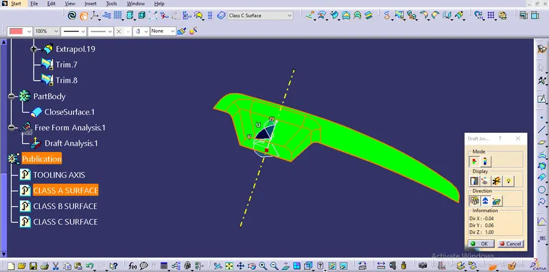
Draft analysis of class A
The compass was just placed to the tooling direction and touching the surface. After the compass was locked to stay fixed and the surface was selected for the draft analysis.
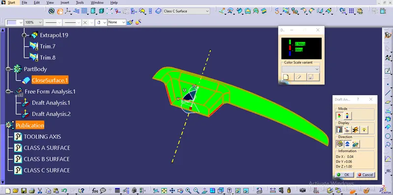
The green color surface shows the draft angle greater than 2.9 deg.
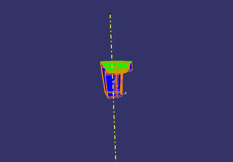
Draft analysis of solid plastic
Here three steps followed to get the required result from the tooling axis.
Step1 ; The compass was just placed on the tooling axis and surface.
Step2 ; The compass was locked to stay fixed.
Step3 ; The surface selected which want to tested.
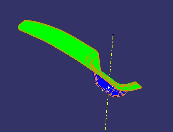
Isometric Front
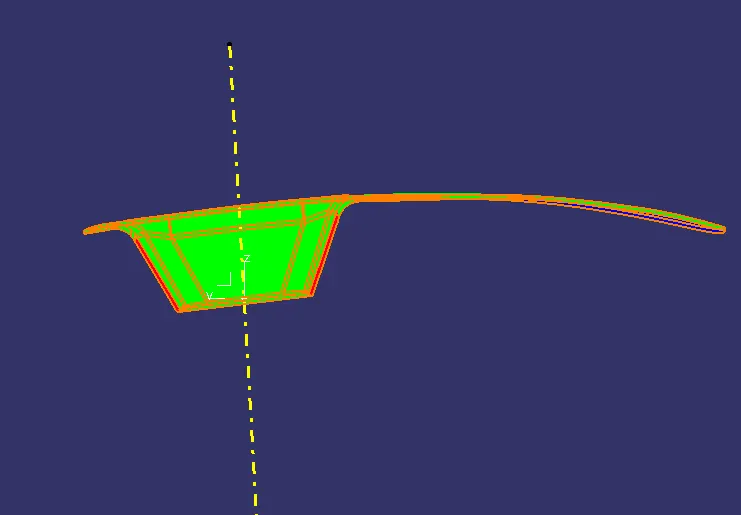
Top Side