Week 9 - Challenge 1 - Base Bracket Design
Base Bracket Design
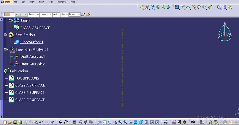
Motive of the challenge to design a base bracket from the class A surface. For that first I have to draw the tooling axis. After tooling axis the following surfaces are created
- Class B Surface
- Class C Surface
- Closed Solid Part
Class B surface and class C surface created from the tooling direction. The closed solid part is created by tool called close surface. After I performed the draft analysis of a class A surface as well as closed solid part.
Tooling Axis
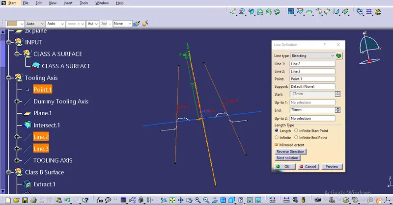
Before the tooling axis a dummy tooling axis is created from a point of a hole. After that a plane was created between the surface and intersection line was created.
After that long distance inclined line is created by the points already present in the intersection line. With the two lines bisecting line is created. that is known as tooling direction.
Class A Surface
Class A surface was already given in the question. I did'nt make any modification on it.
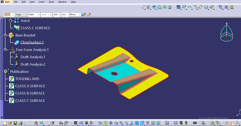
Class B Surface
Class B surface was created by the following tools,
- Exract
- Untrim
- Extropolate
- Trim
- Offset
ribs are extracted and trimmed before offset. And other two surfaces are also extracted and trimmed to ribs. The Offset ditance was 2.5mm.
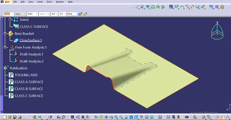
Class C Surface
Class C surface was extruded by tool called sweep. It was created according to the draft axis or tooling axis. Before that the boundary of class A surface was creaded.
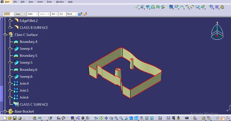
Closed Solid Part
The closed solid part was designed in the part workbench using close surface tool.
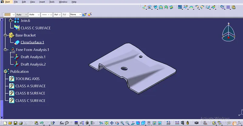
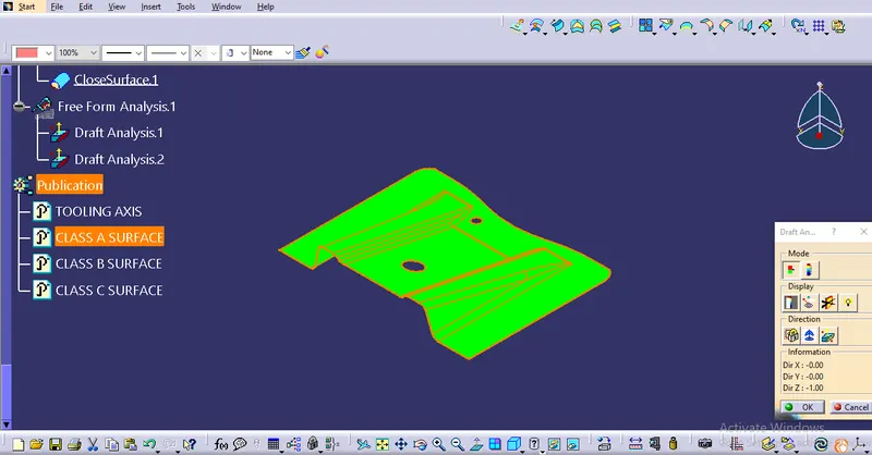
Draft Analysis of Class A surface
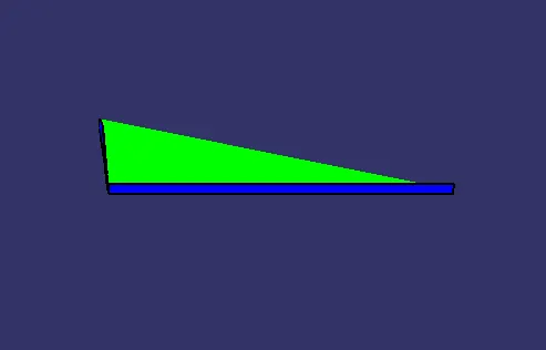
Draft analysis was performed to the class A surface. The compass was applied top of the surface and normal to the tooling axis.
after the surface was selected. It gives the below result.
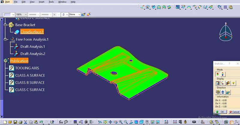
Draft Analysis of Closed Solid Part
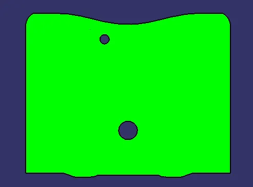
Draft analysis was performed to the closed solid part. The compass was applied top of the solid and normal to the tooling axis.
after the surface was selected. It gives the below result.
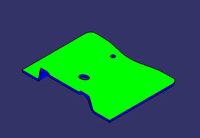
Isometric Front
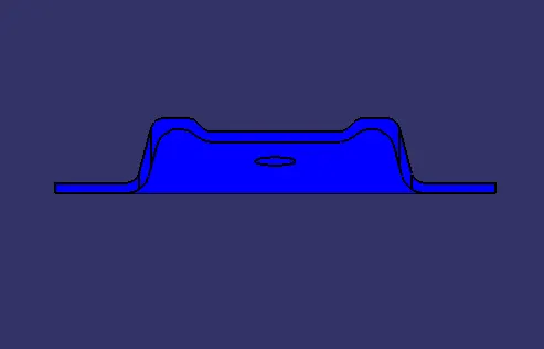
Side top