Week 9 - Challenge 3 - Bumper
Challenge-3 Bumper
Create the Bumper Plastic component through the given Class-A surface. To begin with, the tooling axis for the given Class-A Surface should be created meeting the requirements of the draft angle and at the end perform the Draft analysis on the model.
Bumper
A bumper is a structure attached to or integrated with the front and rear ends of a motor vehicle, to absorb impact in a minor collision, ideally minimizing repair costs.
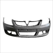
The purpose of bumpers is to reduce or prevent physical damage to the front and rear of vehicles in low-speed crashes. By design, bumpers protect the hood, trunk, grille, fuel, exhaust, and cooling system. A bumper is a shield that is usually made of steel, aluminum, rubber, or plastic.
Design Requirements
- Tooling Axis
- Class A surface
- Class B surface
- Class C surface
- Draft analysis of class A surface
- Draft analysis of solid plastic
Tooling Axis
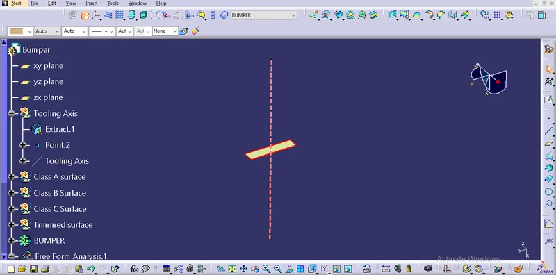
I'm begin with selecting the surface to exract and create a point on the it to draw tooling axis. The surface which is visible in all axis is choosed for exract.Finally tooling axis was published.
Tools used for tooling axis
- Exract
- point
- line
Class A surface
The Class A surface is already given in the question. Using this class A surface class B and class C surfaces are created and published.
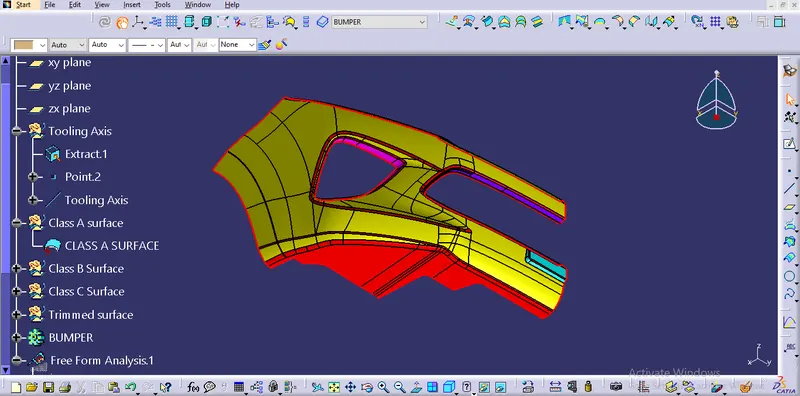
Class B surface
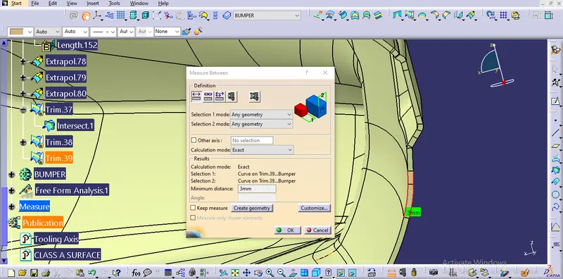
The class A surface was exracted and offsetted to 3mm for getting the 3mm of thickness. After the offset the fillet surfaces are got discontinuous surfaces. There fillets are created and joined to the offsetted surface.
Tools used for class B
- Multiple exract
- Offset
- Exract
- EXtrapolate
- Fillet
- trim
- Join
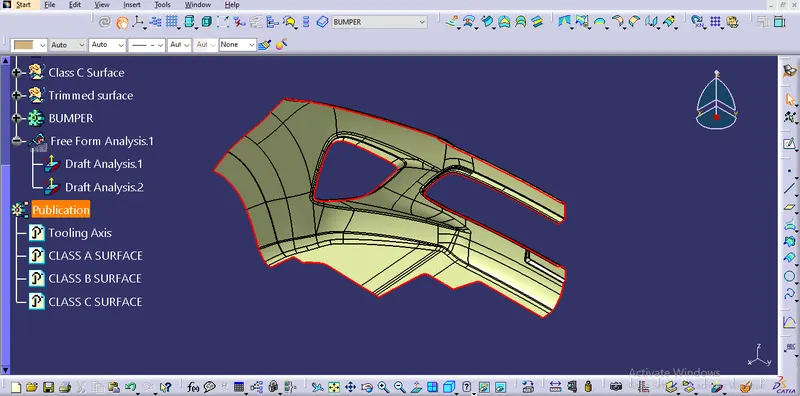
Class C surface
The verticle surface which is between the class A and class B to close the surface is Known as class c surface. This is also published.
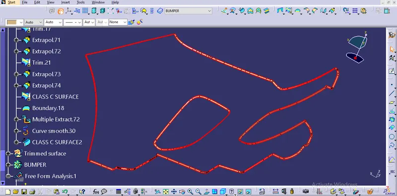
after trimmed the class A,B and C, thickness is measured.
The surface was closed using the tool called close surface. We got solid bumper from the trimmed surface. The tool was selected from the part design workbench.
Part design--> close surface
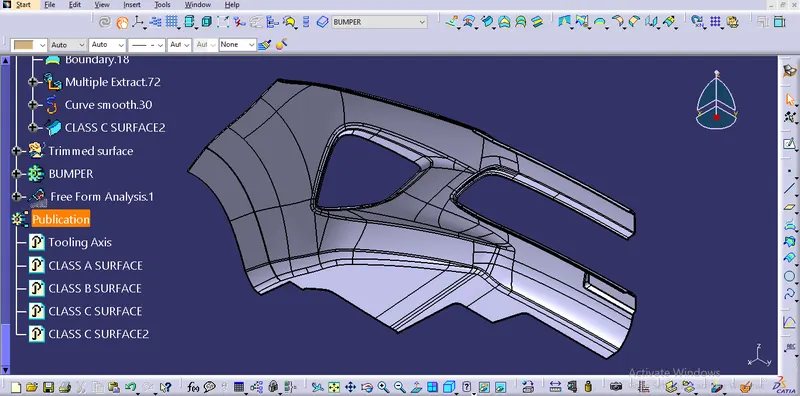
Draft analysis of class A surface
Class A surface and tooling axis were taken for draft analysis. The compass was locked through the tooling axis and surface selectedfor see the color variation.
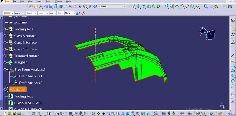
Draft analysis of solid bumper
Solid bumper and tooling axis were taken for draft analysis. The compass was locked through the tooling axis and surface selected for see the color variation.
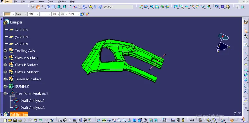
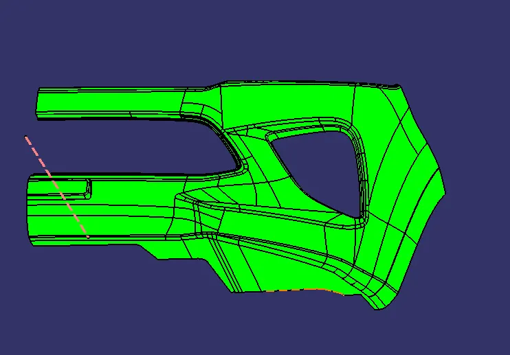
Orthographic view of bumper
Isometric Front
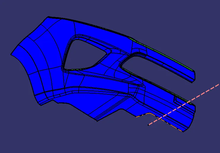
Top Side 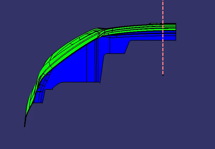
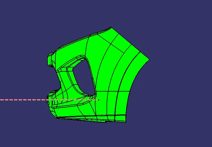
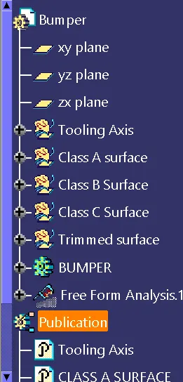
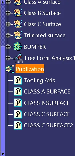
Fully defined tree structure of bumper