Week 6 - Creating connection for Rear door
AIMS:- To do Connections for the rear door.
OBJECTIVES:-
1. To Create and Apply different PIDs for different components.
2. To perform suitable connections.
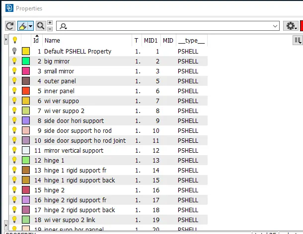
Defining PSHELL properties (PID):-
Define the properties of various components for the rear door model.
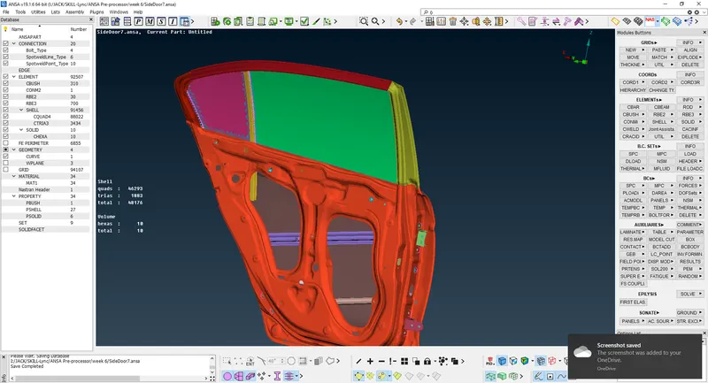
CONNECTIONS Procedure:
In this model, there are various types of connections which are listed below,
1. Bolt Connection (RBE2 Connection)
2. Spot Weld Connection.
3. CBUSH Connection
1. Bolt Connections in NASTRAN Deck:-
This type of connection is used in places where the bolt and nut are used.
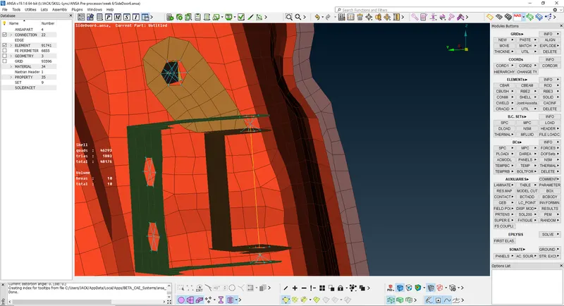
In NASTRAN Deck select Elements>RBE2>Many Nodes. Select the nodes to form the RBE2 element.
It will form a cluster RBE2 connection with one master node.
To create a stem of the bolt Select Elements>RBE2>Two Node. Select the master nodes of two RBE2 elements.
Bolt connection using Assembly deck:
In this method, the bolt connection is made by using reference points.
1. Create a point at the center of the hole. Select Points>On COG>Edges from Topo module and select the edges
of the hole on which you need to create a point. If you have more the two holes try to select the middle one.
2. Now the Point is transformed into a Bolt connection by using Transform>3D Points Option in the Assembly deck.
3. Select Bolt from the list and click Ok. The 3D point is converted into a Hexagon shaped point representing the Bolt connection.
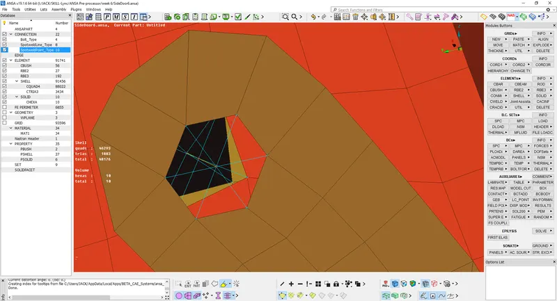
4. Select the Connection manager from the Assembly Deck. select the three parts as p1, p2, and p3. Click on the FE rep type and ANSA will show the list of connections in ANSA, from the list select Bolt. Give search distance of 50. When you click Apply and Realize ANSA will show the bolt connection as shown below.
2. Spot weld connection:-
1. Create the points where the spot welds need to be applied using Points>On COG in Topo Module. Transform the Points into Weld Spots using Transform option in Assembly deck.
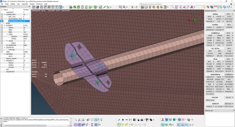
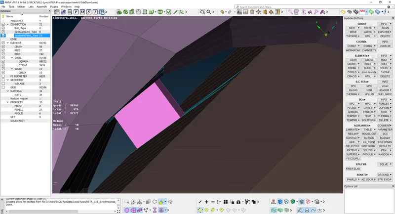
2. In Connection Manager from the Assembly deck, select the Weld spots and click Ok. Assign P1 and P2. In FE Rep Type List, select RBE3-HEXA-RBE3.
3. Once all the details were entered, Click on Apply and Realize. ANSA will Create the spot weld on the places where the points were created as shown below.
3. CBUSH Connection using RBE3 elements:
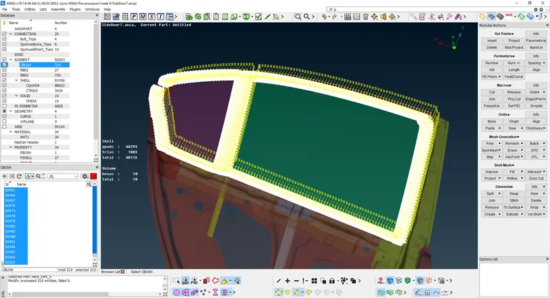
The glass part is connected with the PBUSH connection. Select the edges of the glass and create the curve and copy the curves at a distance of 10,
Convert them to spot weld and select the connection with the given appropriate value in the connection manager by putting S = 10, P1, and P2 as
require. The PID for the bush is given with stiffness value. k1 to k3 = 0.001 and k4 to k6 = 10. Give search distance of 60.
Orientation of CBUSH:-
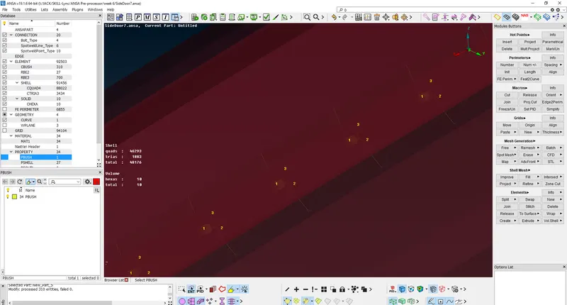
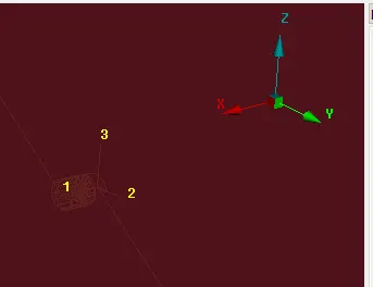
To orient the bush elements, go to Database->Elements>CBUSH. ANSA will list the CBUSH elements in the CBUSH dialog box. Select all the CBUSH elements, Right Click>Modify. A modify window will pop up in modify rules from the dropdown list select Orient and give With Cord then Click on ‘+’ to add CID and give value 0. The changed orientation is shown below as according to x,y,z as 1,2,3.
4. DEFINE THE MASS for DOOR HANDLE:-
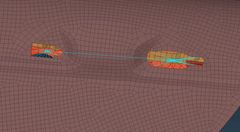
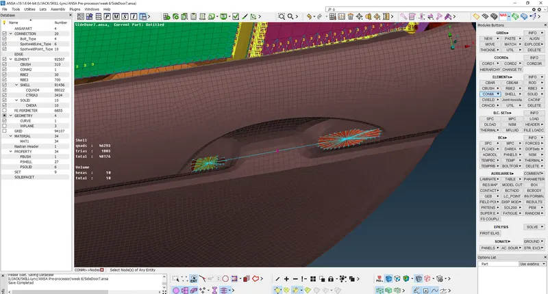
1. Create an RBE2 connection on the holes of the handle using RBE2> Many Nodes from the Nastran Deck.
2. Create an RBE2 connection using the master nodes of the two RBE2 Elements using RBE2>Many Nodes from the Nastran Deck. The Master node of the RBE2 element will be the COG of the Part.
Apply Mass:-
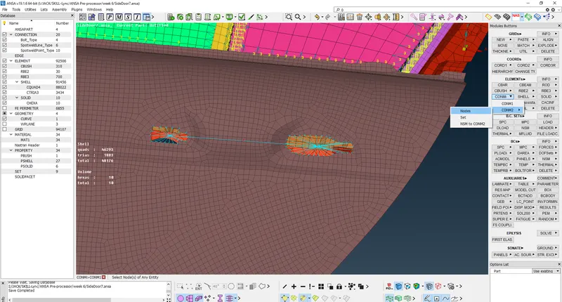
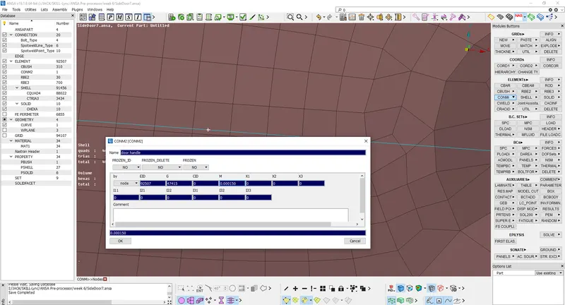
To apply mass, select CONMi->CONM2->Nodes from the Nastran deck, select the Master Node and Middle Click. ANSA will show the CONM2 dialog box in which, enter the mass value of 150 gram = 0.000150 tonnes.
LEARNING OUTCOMES:-
1. Obtained a good knowledge of connections for NVH simulation.
2. Learned to give connections in complex parts.
3. Learned to apply mass on the COG of elements that weren’t captured in the model.