Week- 5 - Solid meshing
Aim: To check the geometric error and mesh the surface of the Rear view mirror componant.
Procedure:
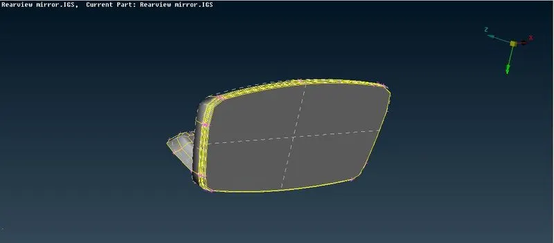
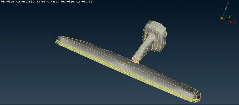
- The actual model is look like this and then need to performed the geometry check and the any errors are formed are fixed. Below shown the actual model.
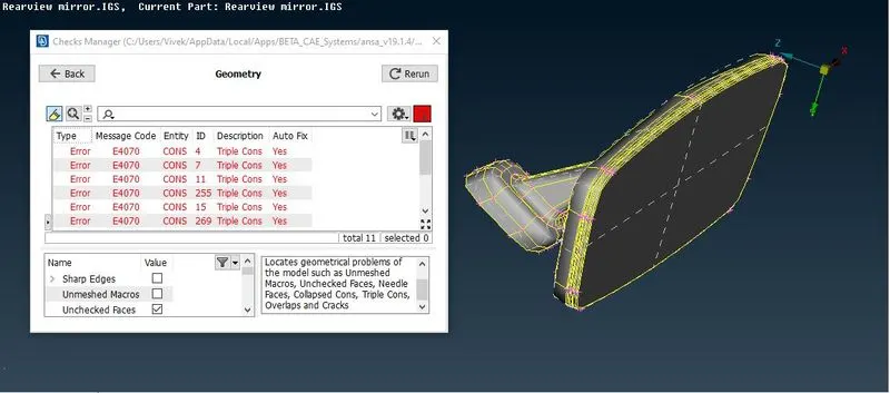
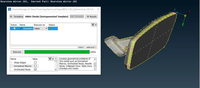
- The geometry check is done and the errors are fixed using the Auto Fix commnad. And the result is shown below. So there are no errors now and the componant is ready for next operations.
- After fixing the errors now next is to assign quality criteria. So the meshing can be done correctly. The quality criteria and the mesh parameter is to be assigned for the Shell and solid mesh.The given componant is solid so we have to perform solid meshing.
For Shell Meshing
|
S.No |
Quality Criteria |
Value |
|
1 |
Target/Average length |
1 |
|
2 |
Minimum Length |
0.5 |
|
3 |
Maximum Length |
2 |
For Solid Meshing
|
S.No |
Quality Criteria |
Value |
|
1 |
Tet collapse |
0.2 |
- The quality criteria and the mesh parameter are given from the Utilities option which is shown as below:
1. Quality Criteria for Shell mesh 2. Quality criteria for Soldi mesh
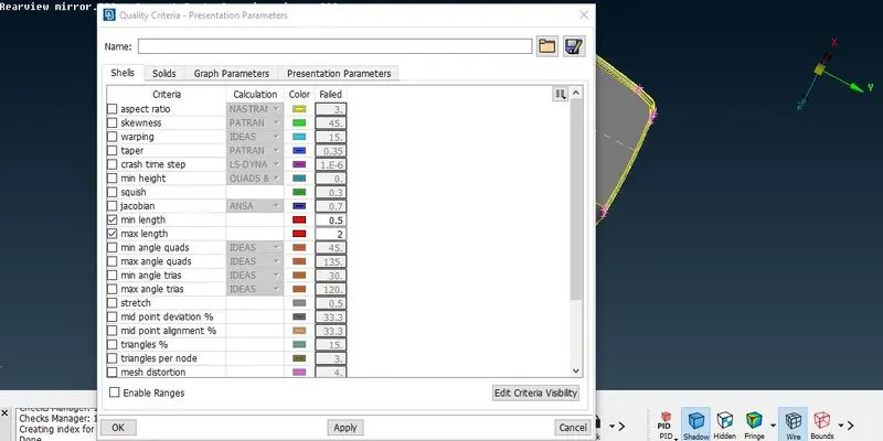
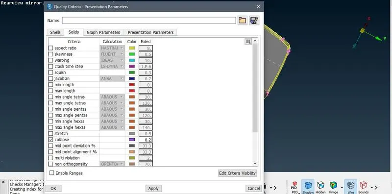
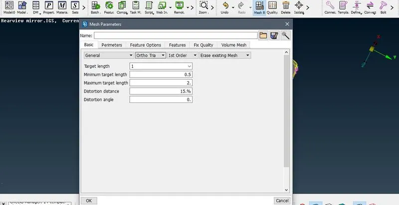
3. Mesh Parameter :
- In mesh parameter the the value of average length , minimum and maximum length is to be put, and the and the mesh pattern is to be selected as Ortho Tria.
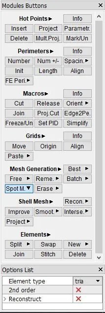
- Now meshing opertation is to be performed. For that select the Mesh module and then select Mesh Gerneration> Spot mesh.
- Now for for diffenerent surface different mesh patter is used.
- For flat surfaces we will use normal trias and for curve surface we will is ortho trias.
- The reason that we use normal and ortho trias is that the ortho trias took more computational time so just to save the time we use normal trias on flat surface.We can change the trias as shown below:
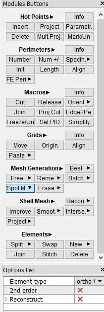
- By using this we can mesh the given componant. So after compliting the meshing and there is no OFF elements and all the length criteria are fulfilled the final componant will look like
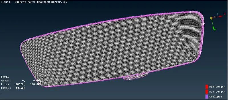
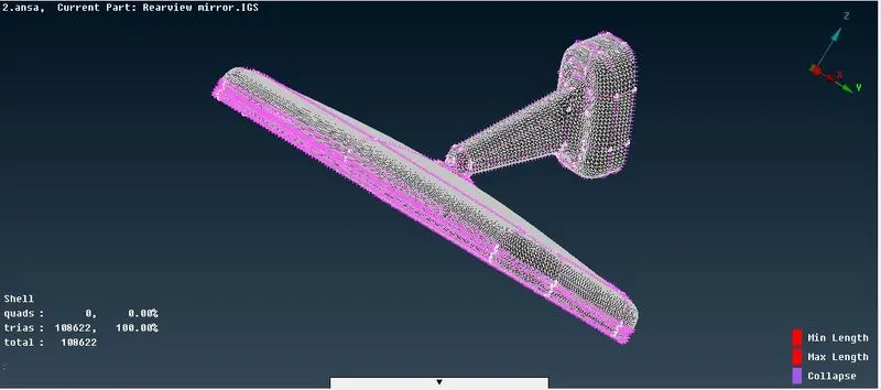
- Now the shell meshing is done we have to perform solid meshing. For solid meshing the first step is to assign the volume to the componant so the volume mesh can be generated.
- So this is done by Volume mesh module. Select Volumes> Define> Manual>Auto so you have to select each volume with the same process.The steps are shown below:
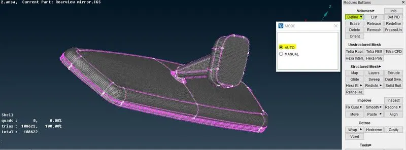
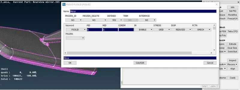
- Now the Volume is assigned the next is the volume meshing for that select list and select the componant and click on the remesh. Select Tetra Rapid or Tetra FEM.
- Now then use the command Unstructured>Tetra RAPID/ Tetra FEM to deploy the tetra elements.
- In order to get better result use Improve> Reconstruct command.
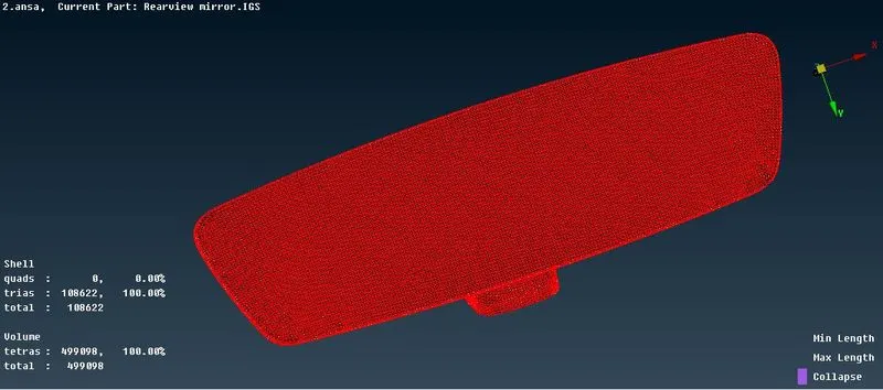
Now the quality that model needs to be checked for Tet collapse. If there is any off element under this criteria it has to be removed.
The final componant will look like this:
Learning Outcomes:
- Got knowldge about the solid mesh. And how to perform the volumetric meshing.
- How to assigne the volume.
- Got to know how the untructured volume meshing look like.
Conlusion: The solid meshing is done on the rearview mirror. The geometry cleanup is done with no error. And the shell meshing and solid (volumetric) meshing is done with no OFF element.