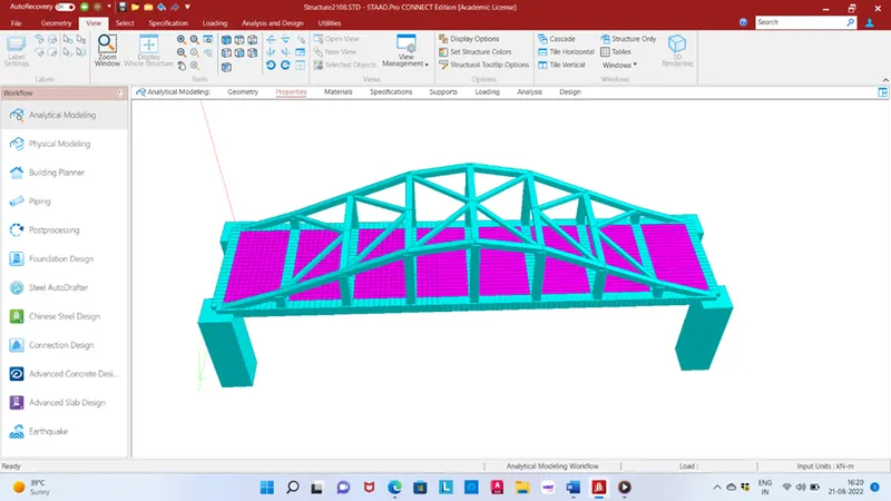
Week 5 Challenge
Aim: Calculate the design wind loads for the bridges and apply the wind load in Staad.pro.
Given data:
Location: Mumbai
Height of bridge: 9m
Pier size: 1.5X1.5m
In open terrain with scattered obstructions of height less than 10m.
Theory:
Wind load is an important consideration when designing and building a barn or other structure. Wind load is the load, in pounds per square foot, placed on the exterior of a structure by wind. This will depend on:
- The angle at which the wind strikes the structure
- The shape of the structure (height, width, etc.)
Preventing wind damage involves strengthening areas where buildings could come apart. The walls, roof and foundation must be strong, and the attachments between them must be strong and secure. For a structure to resist hurricane and weak tornadic winds, it must have a continuous load path from the roof to the foundation -- connections that tie all structural parts together and can resist types of wind loads that could push and pull on the building in a storm. Depending on the location, a typical “wind load” is 80 mph or 16 lb/ft2. Wind loads are calculated as per IS 875 part III 2015 and it is provided the basic wind speed map of India.
Wind exerts three types of forces on a structure:
- Uplift load - Wind flow pressures that create a strong lifting effect, much like the effect on airplane wings. Wind flow under a roof pushes upward; wind flow over a roof pulls upward.
- Shear load – Horizontal wind pressure that could cause racking of walls, making a building tilt.
- Lateral load – Horizontal pushing and pulling pressure on walls that could make a structure slide off the foundation or overturn.
Calculation:
Design wind speed Vz = Vb*K1*K2*K3*K4
K1 = probability factor
K2 = Height factor
K3 = Topography factor
K4 = Importance factor
K1, K2, K3, K4 all are determined from IS code 875 part III 2015
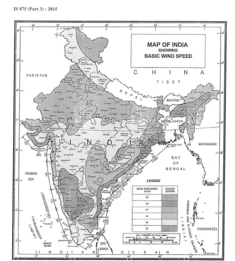
Basic wind speed Vb = 44 m/s ( location Mumbai)
Factor K1
Referring table 1 of IS code 875 part III 2015 For important structure and 44 m/s, K1 = 1.07
Factor K2
Referring table 2 of IS code 875 part III 2015 for height 10m and category 2 structure, K2=1
Factor K3
As per CI 6.3.3 IS 875 part III for up wind slope less then K3 = 1
Factor K4
When the location is within 60km radius of the ocean, the cyclone factor is taken into account K4 = 1.3
Design wind speed
Vz = Vb*K1*K2*K3*K4
= 44*1.07*1*1*1.3
= 61.204 m/s
Wind pressure
Pz = 0.6*
Pz = 0.6*
= 2247.56 N/m2
Pz =2.248 kN/m2
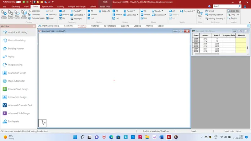
Take a node in x=0, y=0, z=0
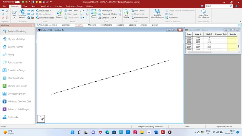
Translational repeat in X direction no. of step 8 with link joint spacing of 3m.
Translational repeat in Y direction in node 2,3,4,5,6 and 7 with distance of 1m,2.5m,3.5m,4m,3.5m,2.5m and 1m respectively and add beam in each node in Y direction.
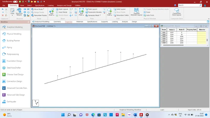
Add beam in XY direction bowstring girder.
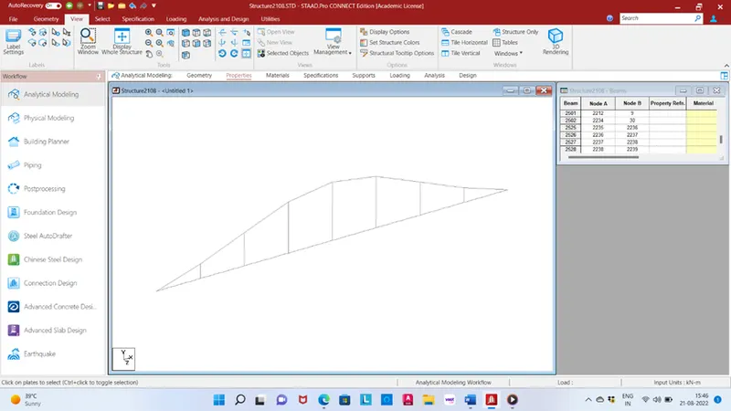
Translational repeat in Z direction one step with joint link spacing 5.5m.
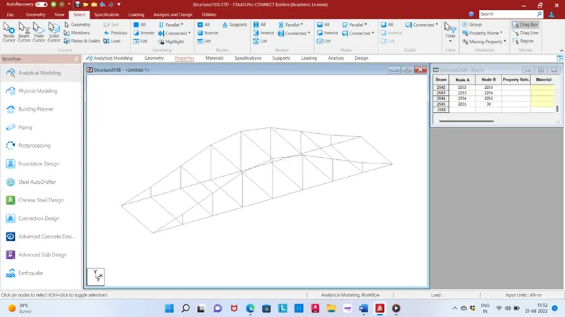
Insert mid node in top beam and add top bracings.
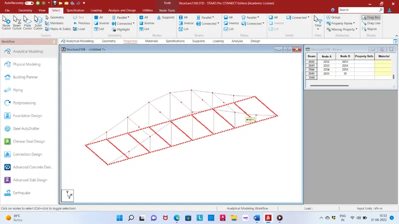
Add one plate in deck slab using translation repeat in X, Z direction using dimension of 0.25m in both direction X, Z then again use translation repeat in Z direction no. of steps 21 with spacing 0.25m.
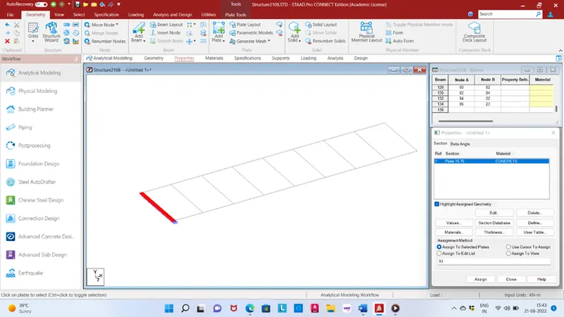
Select all Z direction plate and use translational repeat in X direction no. of steps 95 with spacing 0.25m. Use properties detail give thickness of plate 0.2m.
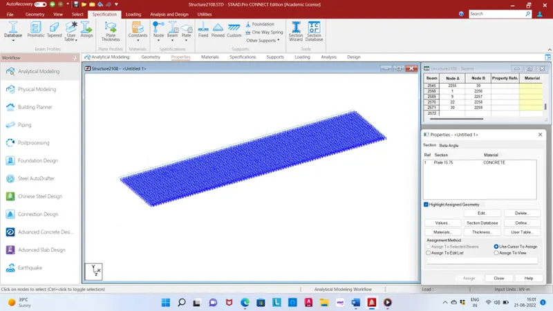
Select all corner node and use translational repeat in -Y direction with link joint spacing 5m.
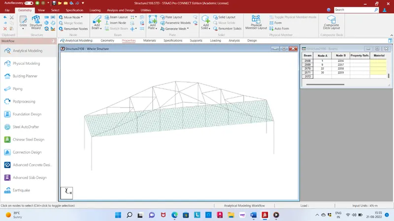
Use properties detail give all square pier dimension 1.5x1.5m.
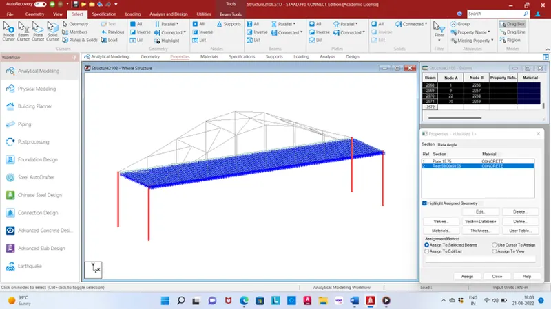
Use properties detail give all dimension main girder and cross girder 0.5m*0.5m.
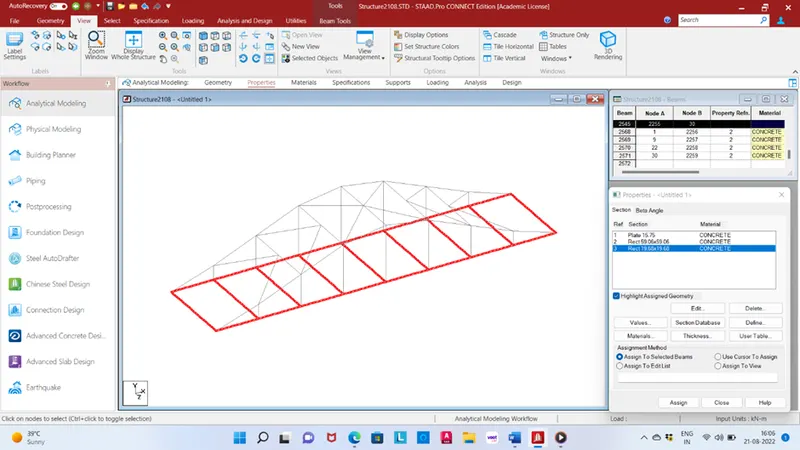
Use properties detail give all dimension to hangar 0.4x0.4m.
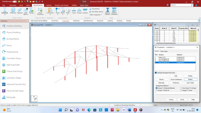
Use properties detail give all dimension to bowstring girder 0.3x0.3m.
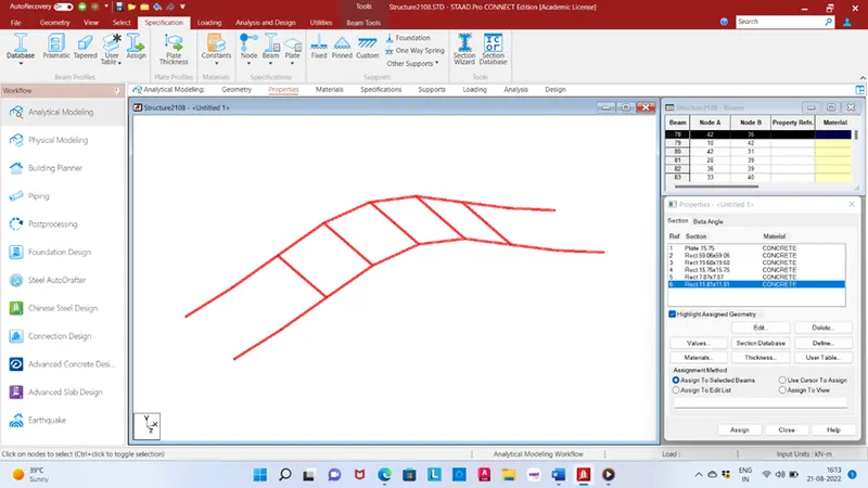
Use properties detail give all dimension to top bracings 0.2x0.2m.
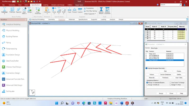
Give fixed support in bottom of pier and assign it.
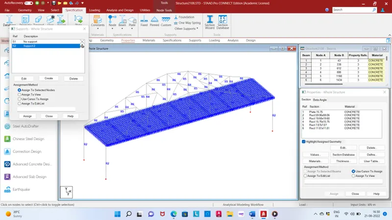
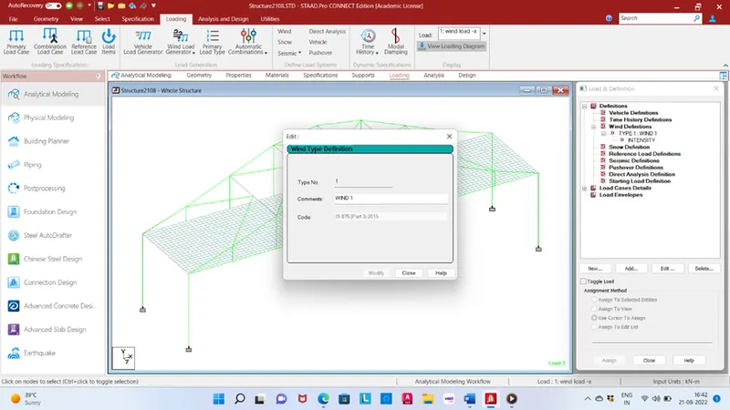
Go to the loading section add wind load in wind definition select code IS 875(part3) 2015.
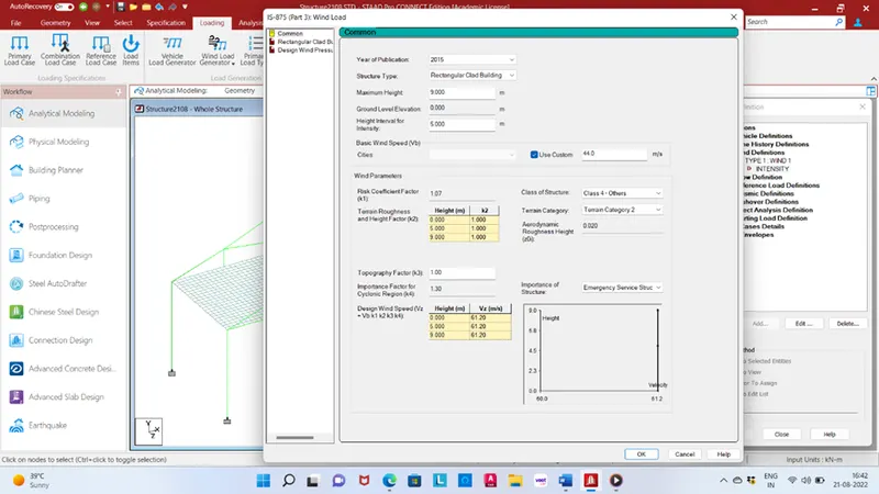
Give all details like as location Mumbai, class of str. Class 4 – other, terrain category 2, importance of str. Emergency service structure and check Vz value same as we calculate manually Vz = 61.2m/s.
Go to load cases details and add load cases wind load X direction with factor = 1, Y range -5 to 4m, X range 0 to 0m, Z range 0 to 5.5m.
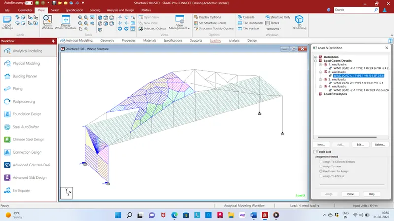
Again add wind load in -X direction with factor = -1, Y range -5 to 4m, X range 24 to 24m, Z range 0 to 5.5m.
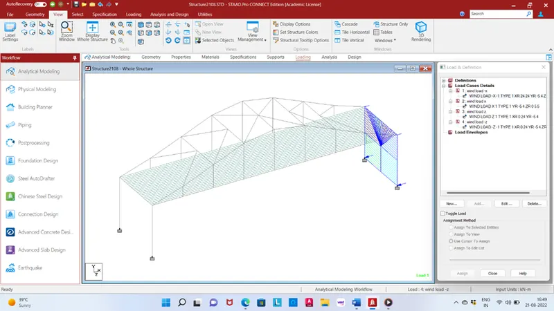
Again add wind load in Z direction with factor = 1, Y range -5 to 4m, X range 0 to 24m, Z range 0 to 0m.
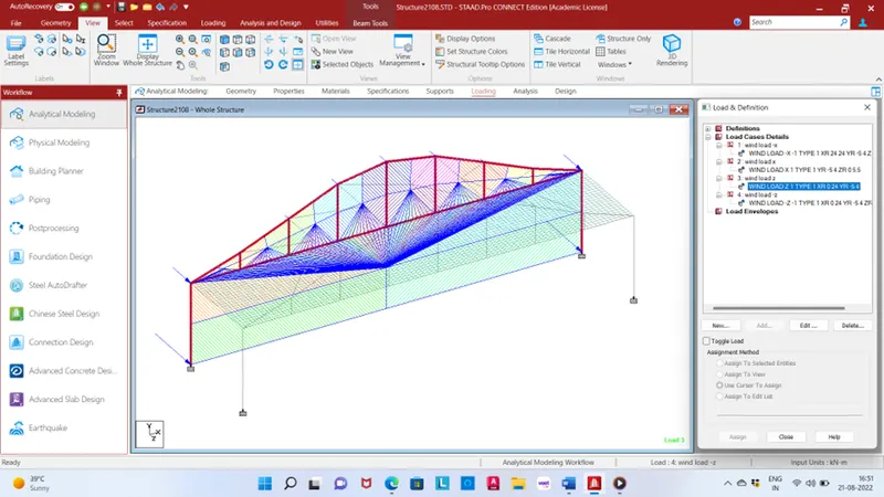
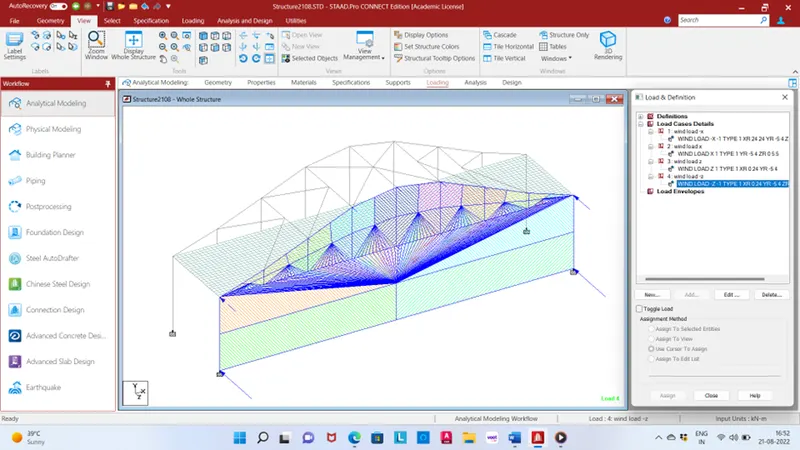
Again add wind load in -Z direction with factor = -1, Y range -5 to 4m, X range 0 to 24m, Z range 5.5 to 5.5m.
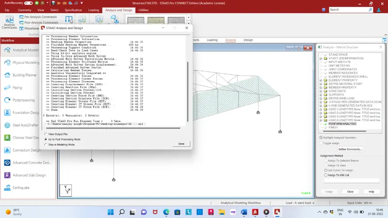
Go to analysis and designs and done perform analysis.
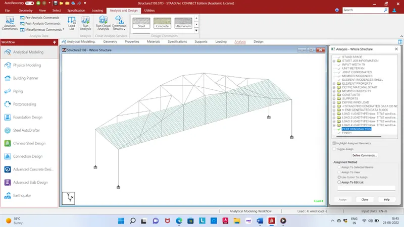
After the perform analysis done go to run analysis when it is successfully run then go to post processing mode.
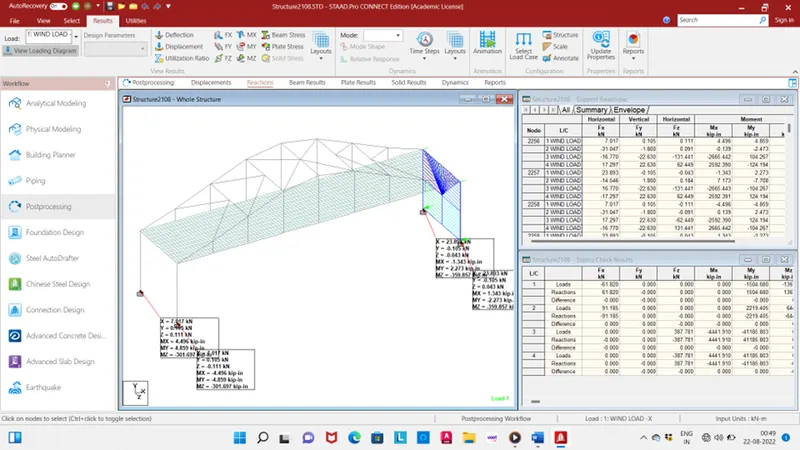
Result:
Reaction in fixed support bottom of pier for load case no.1 wind load in -x direction.
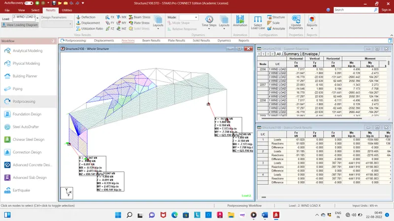
Reaction in fixed support bottom of pier for load case no.2 wind load in x direction.
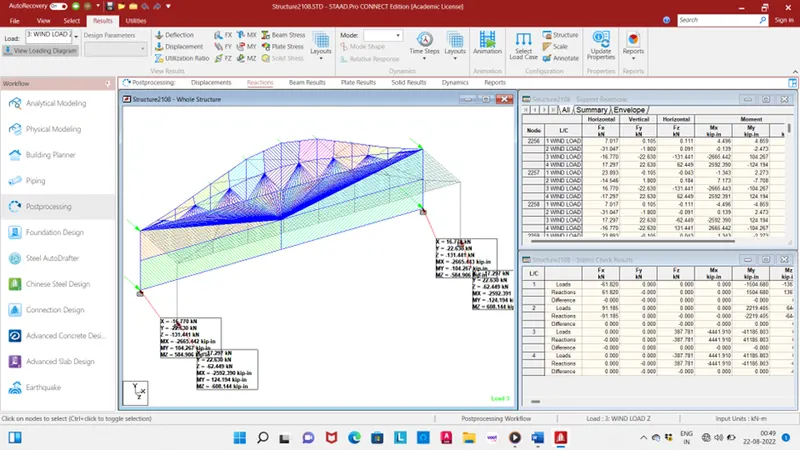
Reaction in fixed support bottom of pier for load case no.3 wind load in z direction.
Reaction in fixed support bottom of pier for load case no.4 wind load in -z direction.
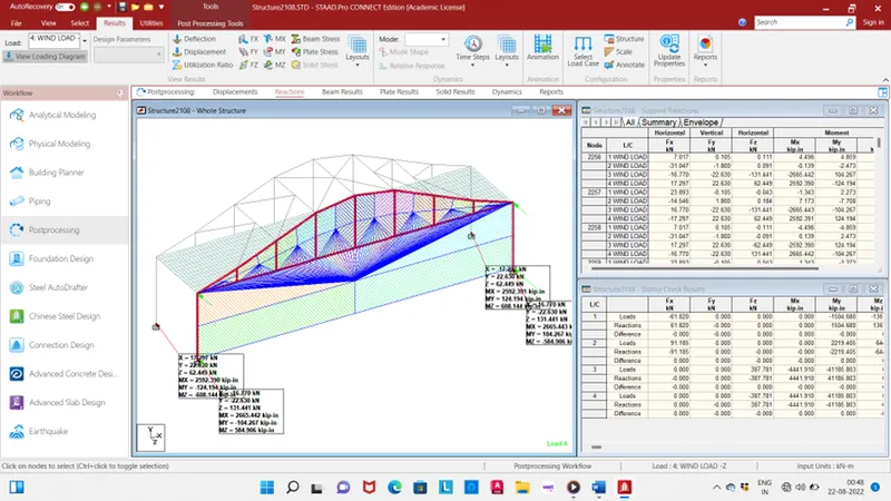
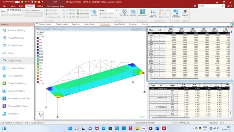
Plate result
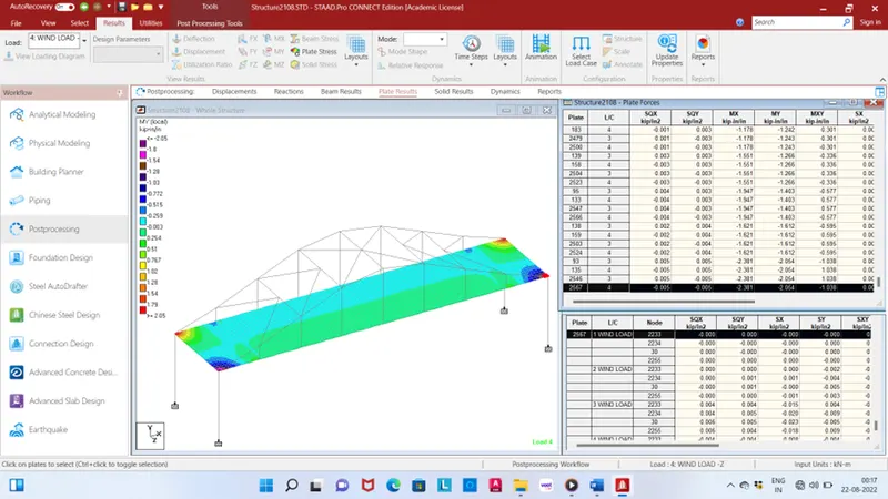
Max. bending moment in X direction plate no. 2567 and load case no. 3 value 2.398 Kip-in/in.
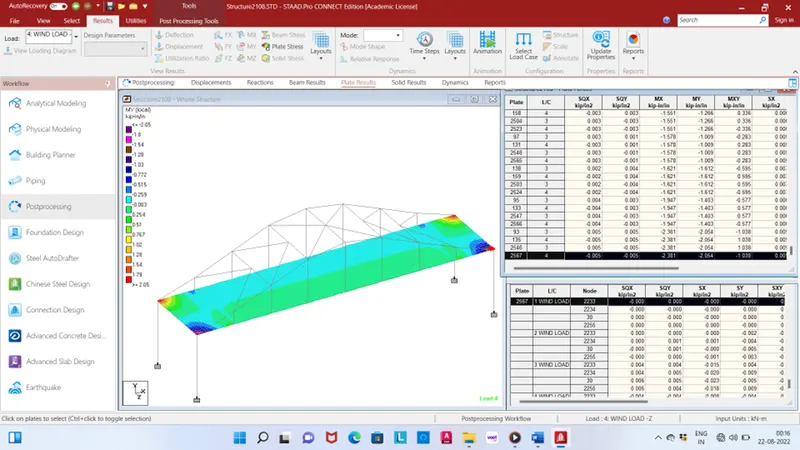
minimum bending moment in X direction plate no. 2567 and load case no. 4 value -2.38 Kip-in/in.
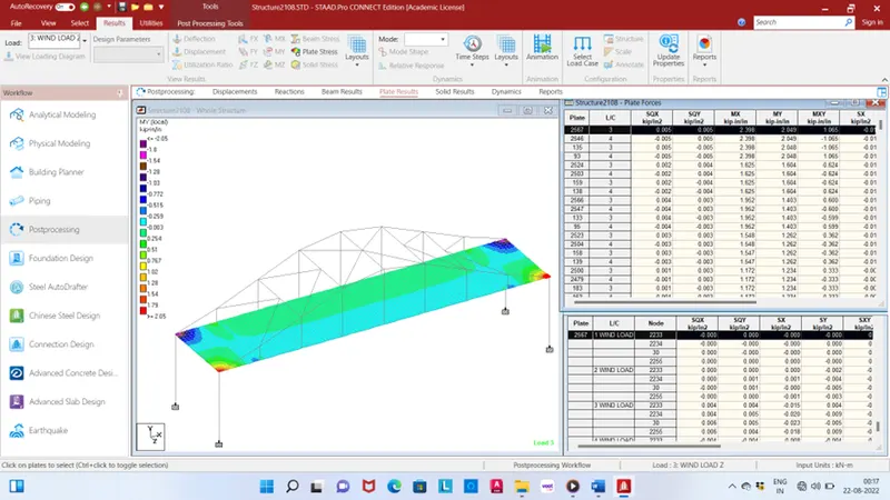
Maximum bending moment in Z direction plate no. 2567 and load case no. 3 value 2.049 Kip-in/in.
Max. bending moment in Z direction plate no. 2567 and load case no. 4 value -2.054 Kip-in/in.
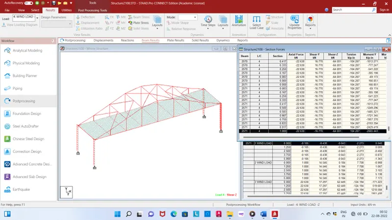
Beam result
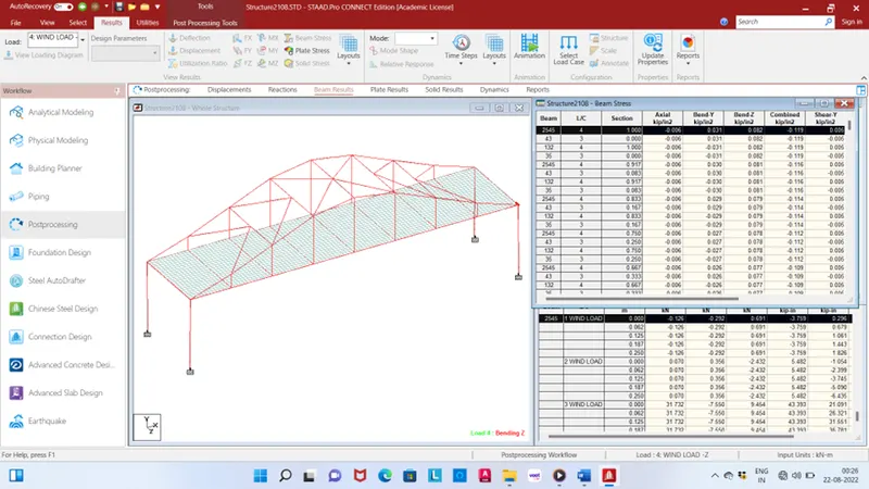
Maximum bending moment in Z beam no. 2545 and load case no.4 value 0.082 Kip-in/in.
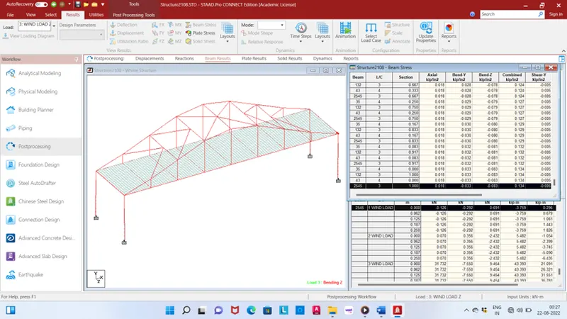
Minimum bending moment in Z direction beam no. 2545 and load case no.3 value -0.083 Kip-in/in.
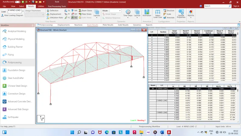
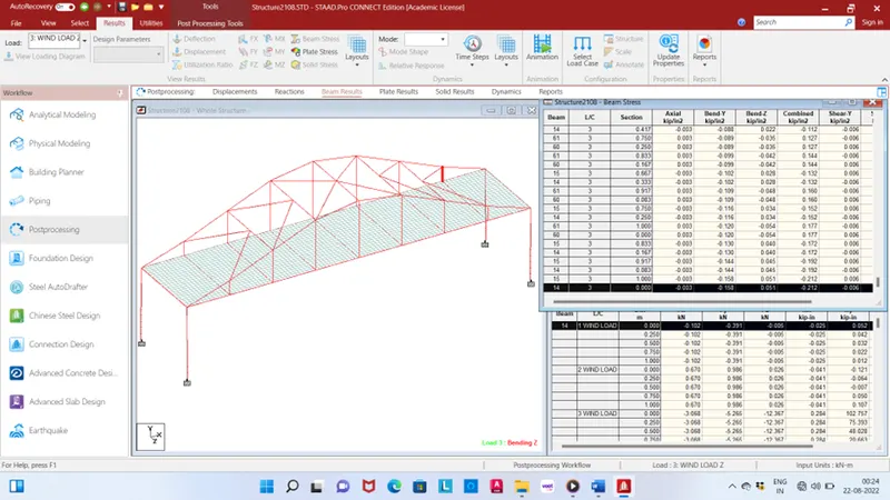
Maximum bending moment in Y direction beam no. 60 and load case no.4 value 0.158 Kip-in/in.
Maximum bending moment in Z direction beam no. 14 and load case no.3 value -0.158 Kip-in/in.
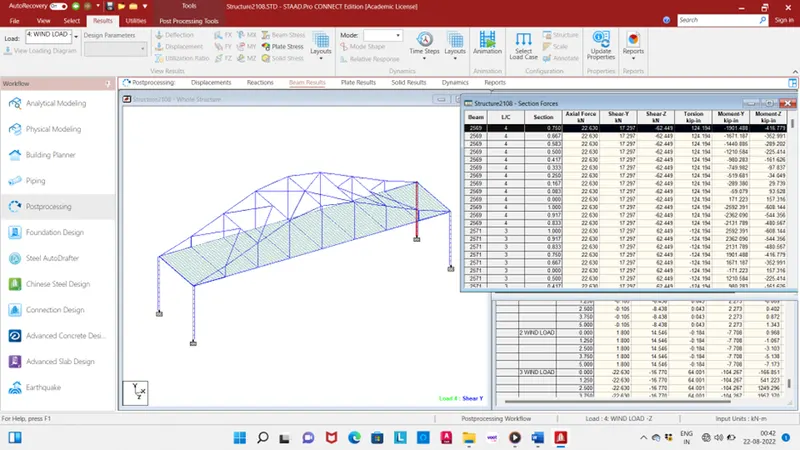
Maximum shear force in Y direction beam no. 2569 and load case no. 4 value 17.297kN.
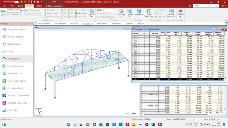
Minimum shear force in Y direction beam no. 2570 and load case no. 3 value -17.297kN.
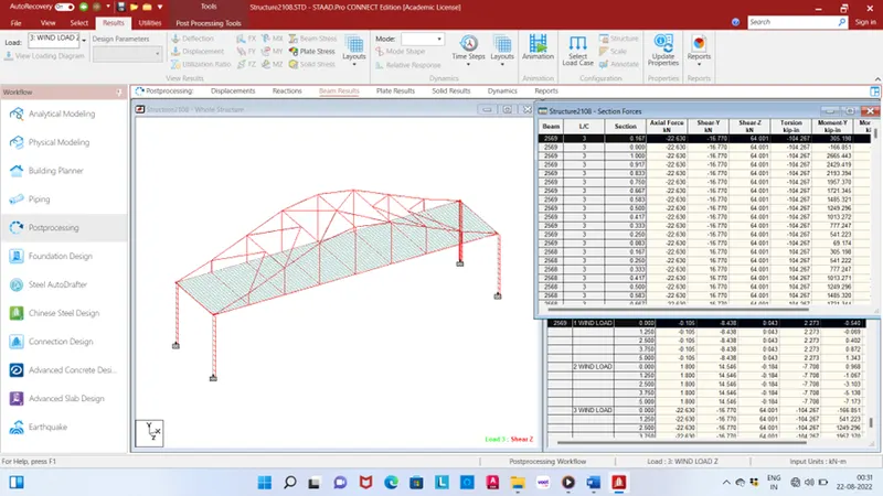
Maximum shear force in Z direction beam no. 2569 and load case no. 3 value 64.001kN.
Minimum shear force in Z direction beam no. 2571 and load case no. 4 value -64.001kN.
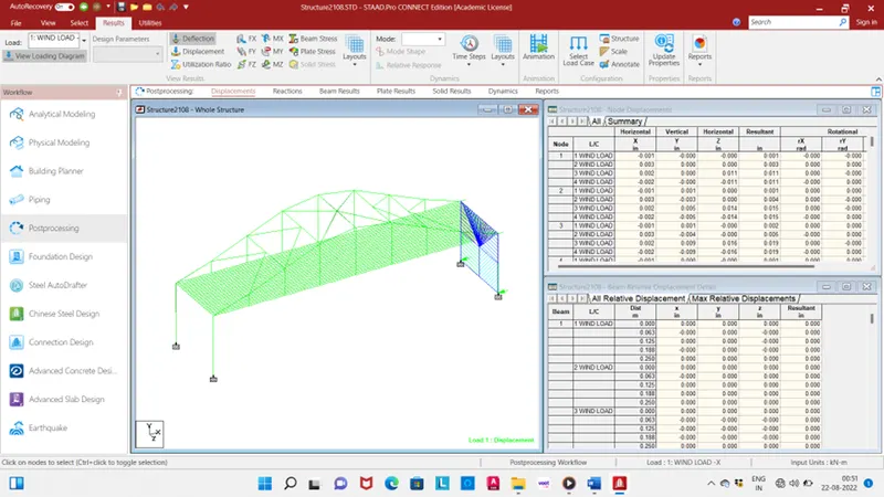
Displacement for different load case.
3D view