Week 3 Challenge
Aim: To apply the IRS live loads and model in Staad pro and perform the structural analysis.
Given data:
Width of the bridge=26
Span of bridge=25m
Pier diameter= 10m
Type of bridge= I girder bridge
Theory:
Live load: The simply supported structures shall be designed for one of the loading envelopes (Light, Medium or Heavy) tabulated in the Annexure I. The loading envelope chosen shall be as per the Rolling Stock planned to be used on the Metro system. Alternately, metro shall work out the EUDL chart for the actual train loads planned to be used and this EUDL chart shall be a part of the DBR.
Loads other than standard trains like track machines, cranes, any new rolling stock etc. which may come on this structure should be within the loading envelope initially decided by the metro as above.
For special structures like continuous structures, cable stayed bridges, etc the actual train loads may be used for design.
The various IRS loads for design of bridges includes
- Metro rail loading
- Broad gauge loading
- Electric train
- Gauge A and gauge B loading
We apply here electric train loading width 1m
Calculation:
No. of load generation= (span length + Total distance of vehicle)/Length of per increment.
No. of load generation = (25+9.178)/1=34.178(approx. 35)
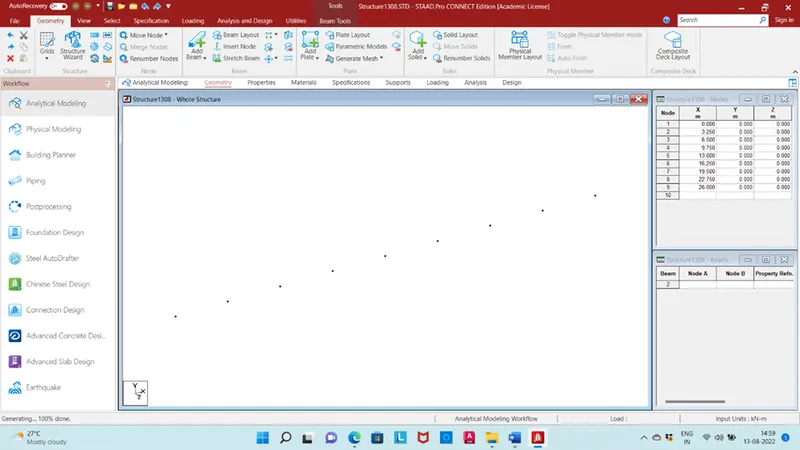
Draw 8 node with distance of 3.25m
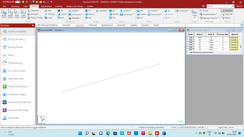
Draw beam with connecting all node
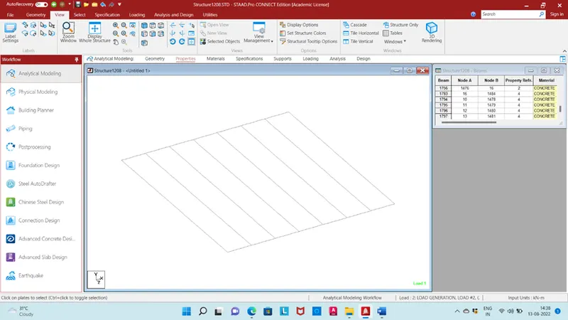
Use translational repeat with link step in Z direction length 25
Insert plat for deck slab
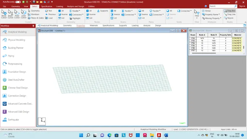
Insert 10m length pier
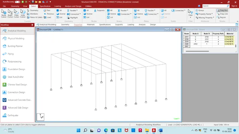
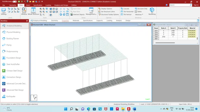
Insert foundation mat plate on all pier
Give properties to all member I beam for main girder, rectangular beam for cross girder, circular beam for pier, plate for deck slab and mat plate for foundation.
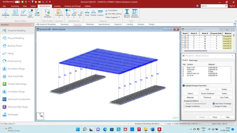
Give foundation support with subgrade modulus 1200 kN/m2/m
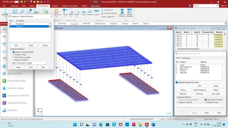
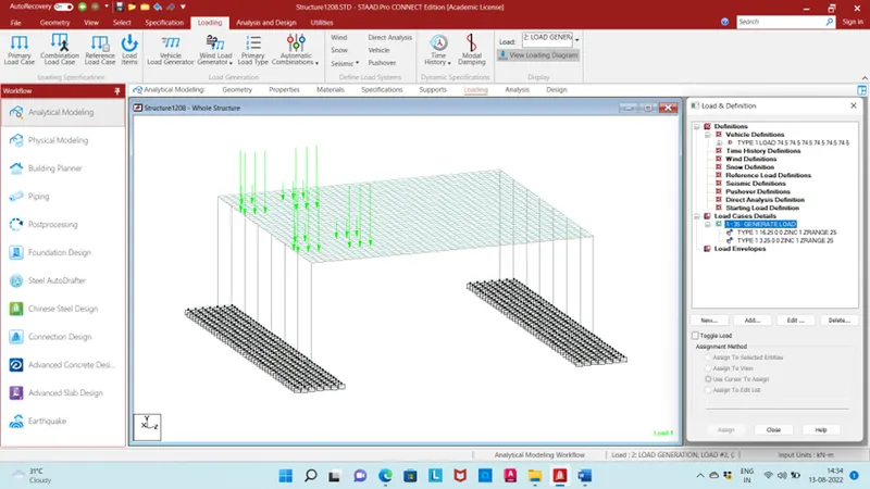
Give IRS live load for electric train width 1m load generation 35 (2time on point of 3.25 and 16.25)
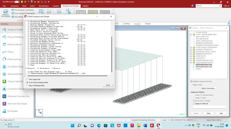
Go to run analysis and go to postprocessing mode
Result:
Displacement of beam
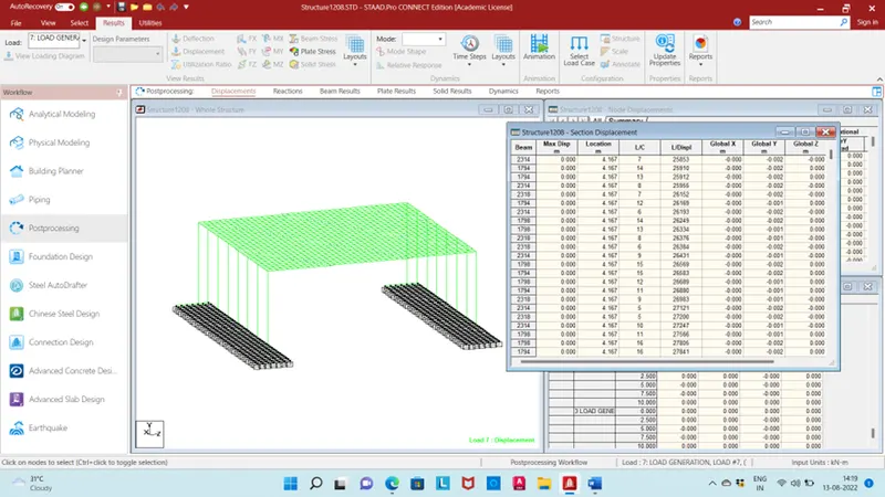
Rection on structure
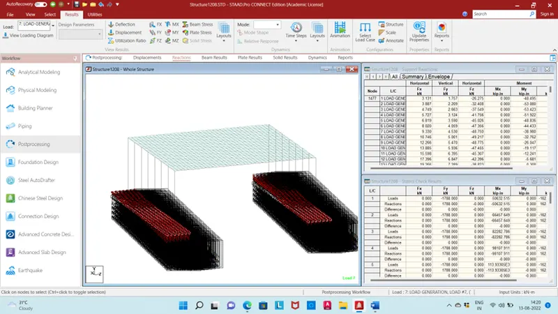
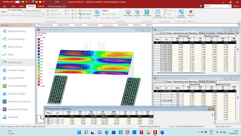
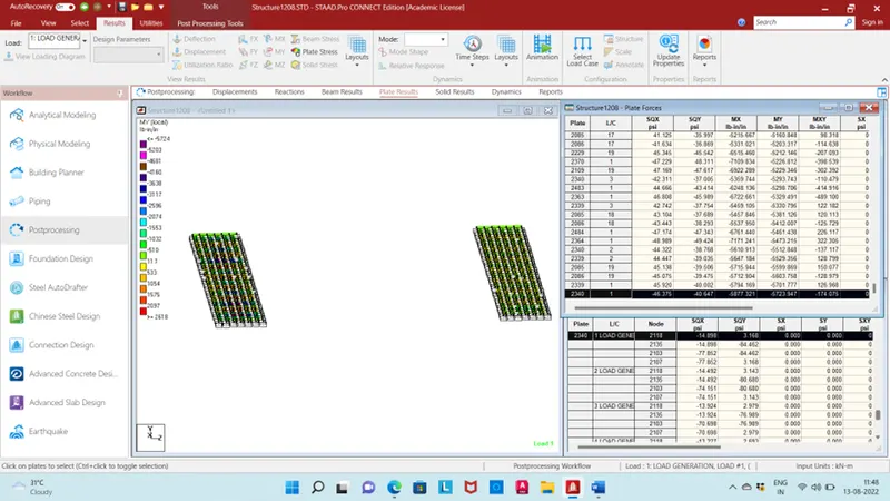
Plate result
Maximum My in deck slab plate no.897 and load case no. 10
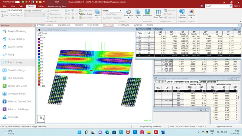
Minimum My in deck slab plate no.881 and load case no. 10
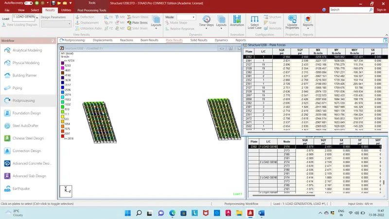
Maximum My in mat plate foundation plate no.2382 and load case no. 1
Minimum My in mat plate foundation plate no.2340 and load case no. 1
Beam result:
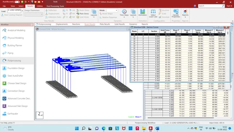
Maximum Shear force in y direction beam no. 33 load case no. 2
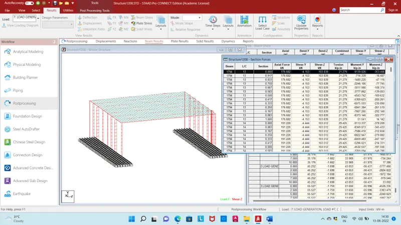
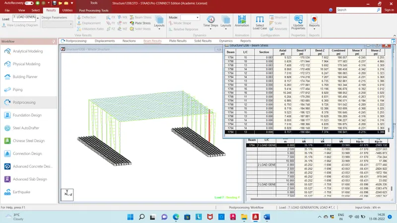
Maximum Shear force in z direction beam no. 1794 load case no. 13
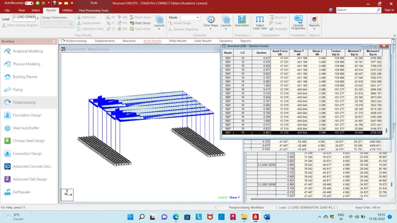
Minimum Shear force in y direction beam no. 1687 load case no. 19
Minimum Shear force in z direction beam no. 2314 load case no. 7
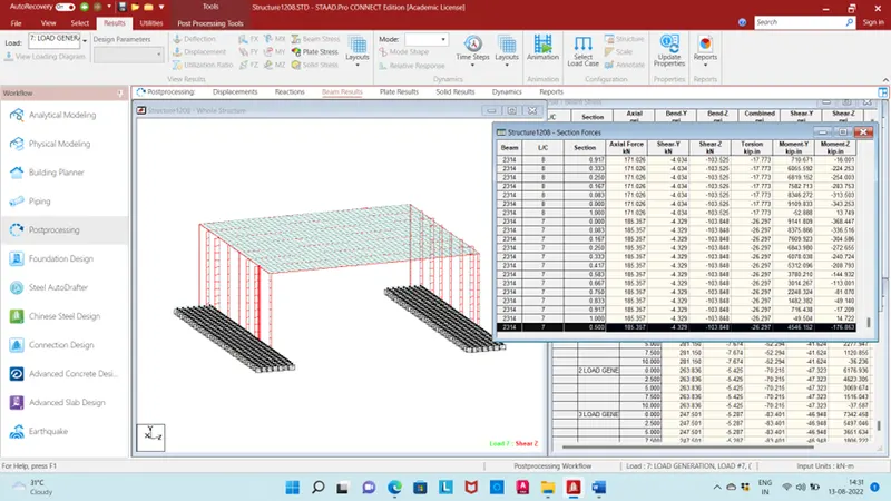
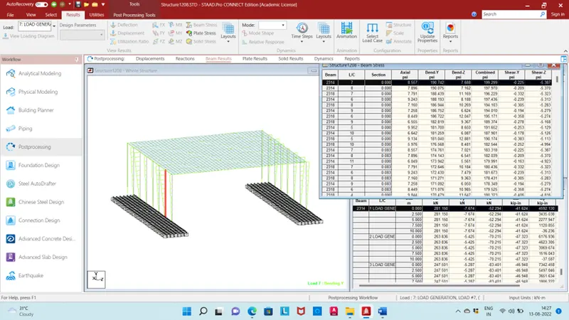
Maximum bending in y direction beam no. 2314 and load case no. 7
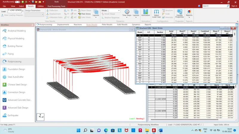
Maximum bending in z direction beam no. 9 and load case no. 7
Minimum bending in y direction beam no. 1794 and load case no. 13
Minimum bending in z direction beam no. 870 and load case no. 12
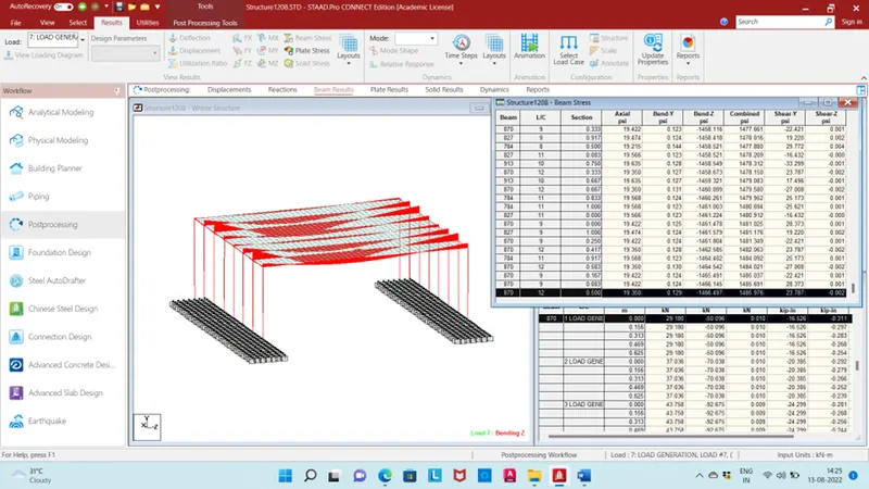
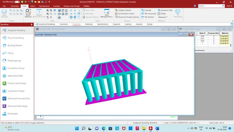
3D view